Supercharge Your Innovation With Domain-Expert AI Agents!

Periphery monitoring system

a monitoring system and peripheral technology, applied in the field of peripheral monitoring systems, can solve the problems of high possibility of false detection of abnormalities, doppler sensors, and inability to accurately monitor abnormalities, and achieve the effect of accurate monitoring and accurate estimation

Inactive Publication Date: 2008-02-19
CIRCUIT DESIGN +1
View PDF8 Cites 5 Cited by
  • Summary
  • Abstract
  • Description
  • Claims
  • Application Information

AI Technical Summary

Benefits of technology

The present invention provides a system for monitoring movements of a mobile object around a vehicle or other compartment using a Doppler sensor. The system can accurately determine if the mobile object is approaching the vehicle or if it is a person trying to enter the compartment. This is important for estimating the risk of intrusion and ensuring safety. The system uses an FFT analysis of the signal from the Doppler sensor to accurately measure the movements of the mobile object. By calculating the total sum of frequency levels and setting a reference level, the system can determine if the movement is abnormal or normal. The system can also update the reference level to a new level if the total sum exceeds the abnormal level. Overall, the invention provides a reliable and effective way to monitor movements and prevent unauthorized access.

Problems solved by technology

However, the above conventional intrusion detection systems can detect intrusion only after a human has intruded into a vehicle compartment, and therefore, it is too late to give an alarm in many cases.
However, the Doppler sensor is susceptible to influences of mobile phone waves, radio broadcasting waves, and the like, and has a high possibility of falsely detecting an abnormality because of the influences.
This phenomenon is generally the same as that caused when a human approaches to a vehicle and is therefore difficult to distinguish from movement of a human.

Method used


Image

  • Periphery monitoring system
  • Periphery monitoring system
  • Periphery monitoring system

Examples


Embodiment Construction

[0035]Hereinafter, an embodiment of the present invention is described with reference to the drawings.

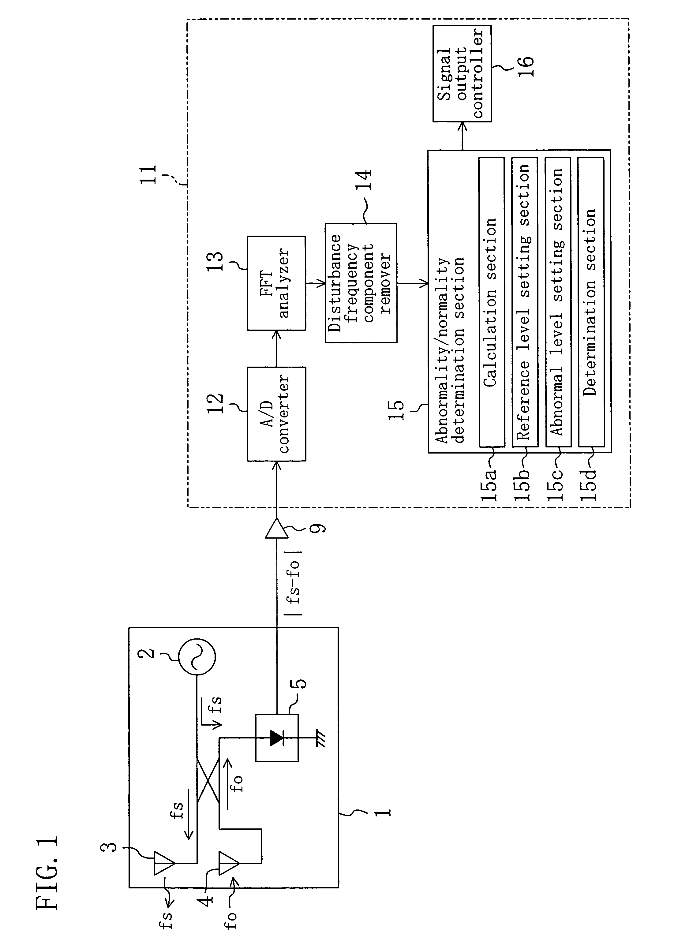
[0036]FIG. 1 shows a structure of a periphery monitoring system according to an embodiment of the present invention. This periphery monitoring system includes a Doppler sensor 1 and a controller 11 for determining whether the periphery status is abnormal or normal based on an output signal received from the Doppler sensor 1 and, if it is abnormal, activating an LED, or the like, as an alarm.

[0037]The Doppler sensor 1 has a dielectric transmitter 2 for emitting a transmission wave having frequency fs (in this embodiment, a microwave of 24 GHz) through a transmission antenna 3. A reflection of the transmission wave by an object is received by a reception antenna 4. The frequency of this reflection wave, fo, varies according to the moving velocity of the object. In the Doppler sensor 1, a Schottky barrier diode 5 outputs the shift in frequency between the transmission wave and the refl...


PUM


Abstract

In a periphery monitoring system for monitoring movements of a mobile object around an installation location of a Doppler sensor, a signal output from the Doppler sensor is subjected to an FFT analysis, and a total sum of the frequency levels of all of the frequency bands obtained through the FFT analysis is calculated at predetermined time intervals. A reference level and abnormal level are set based on the calculated total sum. If the calculated total sum exceeds the abnormal level and falls to or below the abnormal level before a first set period passes since the exceeding of the abnormal level, the periphery status is determined to be abnormal. If the total sum exceeds the abnormal level but does not fall to or below the abnormal level even after the first set period passes since the exceeding of the abnormal level, the periphery status is determined to be normal, and the reference level is updated to a new reference level set based on total sums calculated during the first set period.

Description

CROSS-REFERENCE TO RELATED APPLICATIONS[0001]This application claims priority under 35 U.S.C. §119(a) on Japanese Patent Applications Nos. 2005-016780 and 2005-016783 filed on Jan. 25, 2005, the entire disclosures of the specification, drawings and claims of which are hereby incorporated by reference.BACKGROUND OF THE INVENTION[0002]1. Field of the Invention[0003]The present invention falls within the technical field relating to a periphery monitoring system which uses a Doppler sensor for monitoring movements of a mobile object around the installation location of the Doppler sensor to estimate, for example, intrusion of the mobile object into a compartment of a vehicle.[0004]2. Description of the Prior Art[0005]Conventionally, a system for detecting intrusion into a compartment of a vehicle wherein when a door of the vehicle is opened the system determines it as an abnormality to give an alarm, for example, has been well known. There has also been a system for detecting intrusion o...

Claims


Application Information

Patent Timeline
Patent Type & Authority Patents(United States)
IPC IPC(8): G01S13/62B60R25/10
CPCB60R25/1004G01S13/56G08B13/1627B60R25/1009
Inventor NAKAGAWA, MAKOTOOKADA, HIDEYUKIFUJIWARA, MICHIHIDEMIZUTANI, NORIAKI
Owner CIRCUIT DESIGN
Features
  • R&D
  • Intellectual Property
  • Life Sciences
  • Materials
  • Tech Scout
  • Unparalleled Data Quality
  • Higher Quality Content
  • 60% Fewer Hallucinations
Learn More