Confocal 4-pi microscope and method for confocal 4-pi microscopy

Inactive Publication Date: 2008-02-19
LEICA MICROSYSTEMS CMS GMBH
View PDF12 Cites 9 Cited by
  • Summary
  • Abstract
  • Description
  • Claims
  • Application Information

AI Technical Summary

Benefits of technology

[0010]The task underlying the invention is therefore to suggest a confocal 4-pi microscopy pr

Problems solved by technology

However, the single-photon excitation preferred in confocal microscopy generates secondary maxima of approximately

Method used


Image

  • Confocal 4-pi microscope and method for confocal 4-pi microscopy
  • Confocal 4-pi microscope and method for confocal 4-pi microscopy
  • Confocal 4-pi microscope and method for confocal 4-pi microscopy

Examples


Embodiment Construction

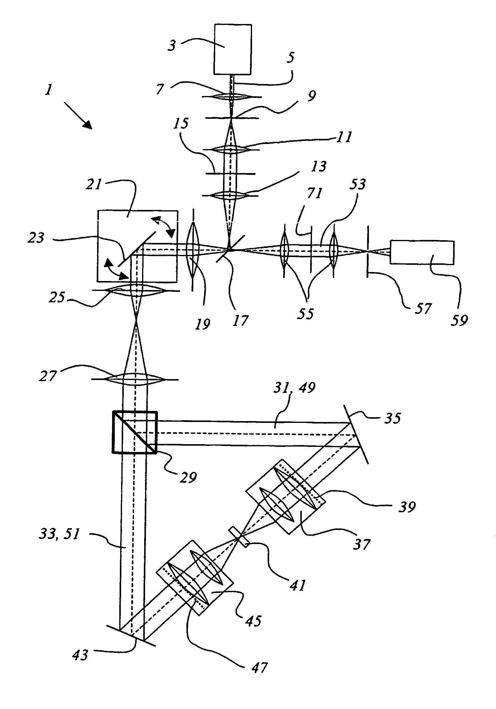
[0043]FIG. 1 shows a confocal 4-pi microscope 1 with a light source 3 that emits illumination light 5. The illumination light 5 is focused with the lens 7 on to the illumination pinhole aperture 9, passes through it, and then passes through the first optic 11, the second optic 13, and a pupil filter 15 that is arranged between the first optic 11 and the second optic 13. The illumination light 5 is reflected from a beam splitter 17, which is designed as a dichroic beam splitter, through the optic 19 to a beam deflector 21 that comprises a cardanically mounted scanning mirror 23. The scanning mirror 23 of the beam deflector 21 is tiltably mounted along two axes so that the illumination light can be deflected and scanned, respectively, by tilting the scanning mirror 23 appropriately. From the beam deflector, the illumination light 5 reaches the scanning optic 25 and then via a tube optic 27 reaches a further beam splitter 29 that splits the illumination light into a first partial illum...


PUM


Abstract

The invention relates to a confocal 4π microscopy method which is characterized by coherently illuminating a sample from two sides by one objective each with illumination light which has at least one illumination wavelength whereby a stationary illumination wave having a main illumination maximum and secondary illumination maxima is produced by interference of the illumination light in the sample. The detection light emitted by the sample has at least one detection wavelength and is detected through the two objectives. The detection light is made to interfere, thereby producing in the sample a detection pattern having a main detection maximum, secondary detection maxima and detection minima in such a manner that the secondary illumination maxima and the detection minima overlap at least partially.

Description

CROSS-REFERENCE TO RELATED APPLICATIONS[0001]This application is a national stage of PCT application serial number PCT / EP04 / 000029 filed on Jan. 6, 2004, which claims priority to German application serial number DE 103001573 filed on Jan. 7, 2003, both of which are incorporated herein by reference in their entirety.BACKGROUND OF THE INVENTION[0002]The invention relates to a method for confocal 4-pi microscopy.[0003]The invention furthermore relates to a confocal 4-pi microscope with a light source that produces an illumination light that exhibits at least one illumination wavelength, and that is directable from two sides by one objective each onto a sample, whereby a stationary illumination wave having a main illumination maximum and secondary illumination maxima is produced by interference of the illumination light in the sample, and having a detector to detect detection light emitted by the sample that passes through both objectives and that exhibits at least one detection wavelen...

Claims


Application Information

Patent Timeline
IPC IPC(8): G01B9/02G01J3/45G02B21/00
CPCG02B21/0032G02B21/0056G02B21/0076
Inventor BEWERSDORF, JORGGUGEL, HILMAR
Owner LEICA MICROSYSTEMS CMS GMBH
Why Eureka
Try Eureka