Method and apparatus for transforming coordinate systems in a telemanipulation system

a technology of coordinate system and telemanipulation system, which is applied in the field of telemanipulation using telepresence, can solve the problems of inability of operators to control the movement of manipulators, and inhibit the ability of operators to control them with dexterity and rapidity

Inactive Publication Date: 2008-02-19
SRI INTERNATIONAL
View PDF32 Cites 215 Cited by
  • Summary
  • Abstract
  • Description
  • Claims
  • Application Information

AI Technical Summary

Problems solved by technology

This will cause the manipulators to move in an awkward manner relative to the viewing position, inhibiting the operator's ability to control them with dexterity and rapidity.
However, it is often unavoidable in applications such as laparoscopic surgery to move the laparoscope in order to obtain the best possible image of the abdominal cavity.

Method used


Image

  • Method and apparatus for transforming coordinate systems in a telemanipulation system
  • Method and apparatus for transforming coordinate systems in a telemanipulation system
  • Method and apparatus for transforming coordinate systems in a telemanipulation system

Examples


Embodiment Construction

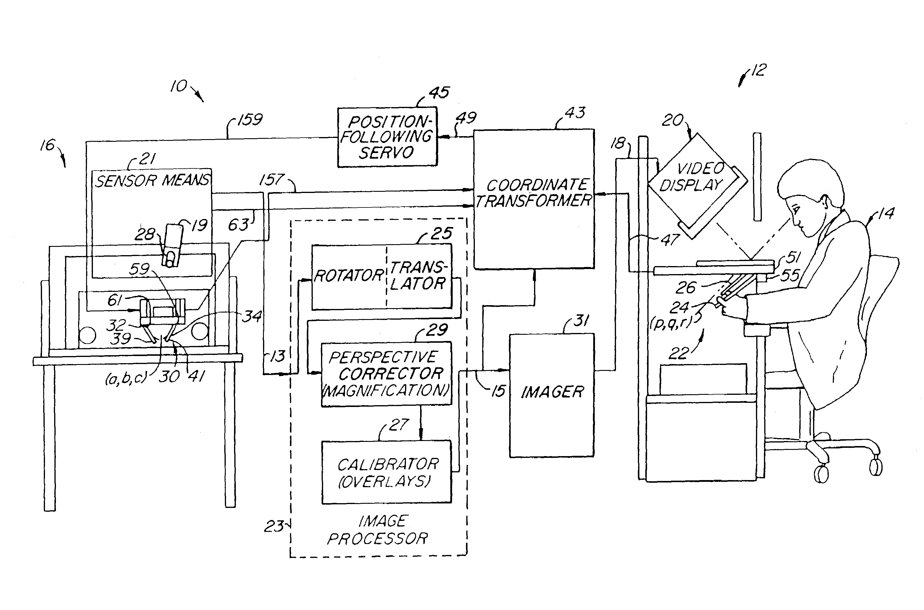
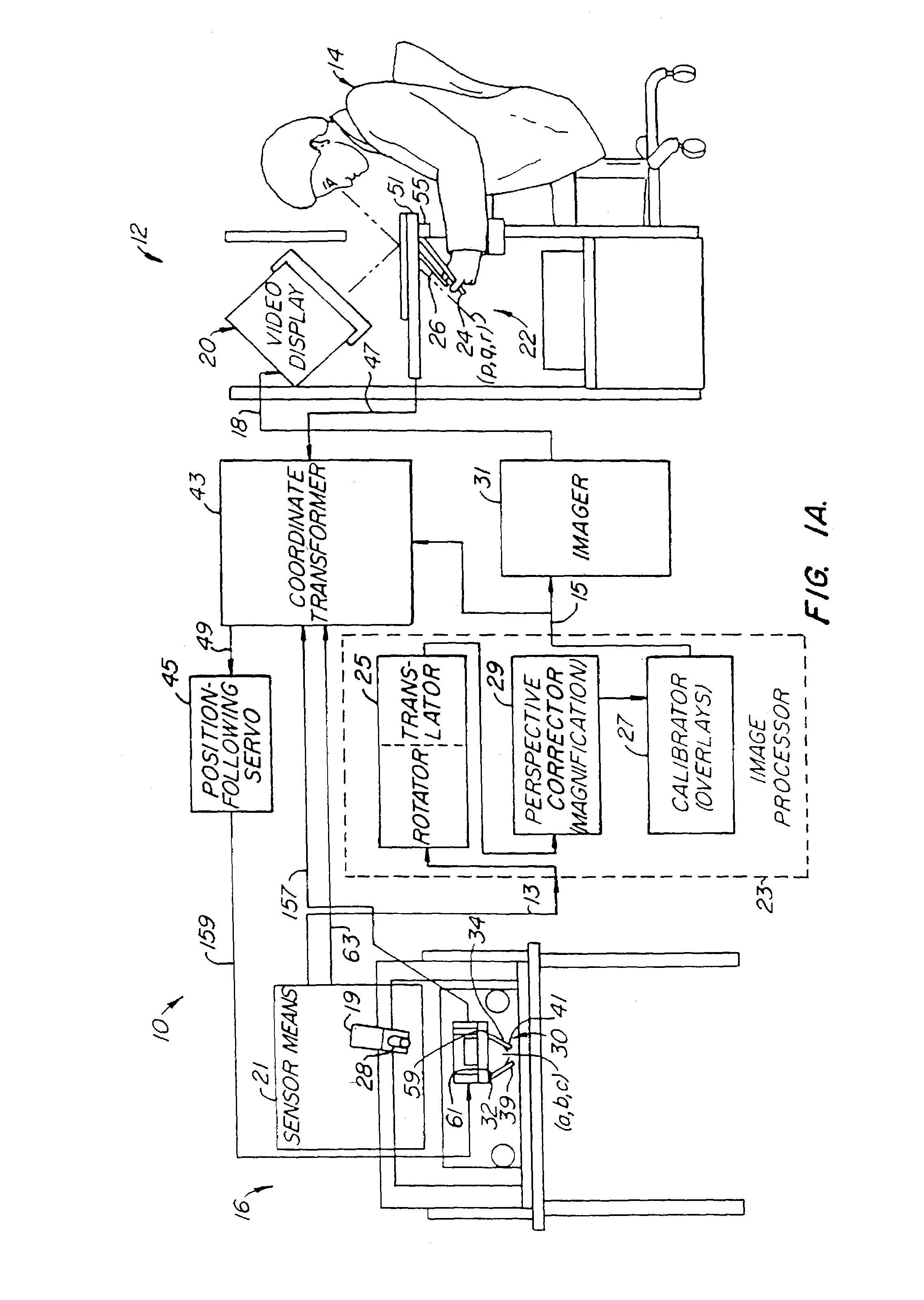
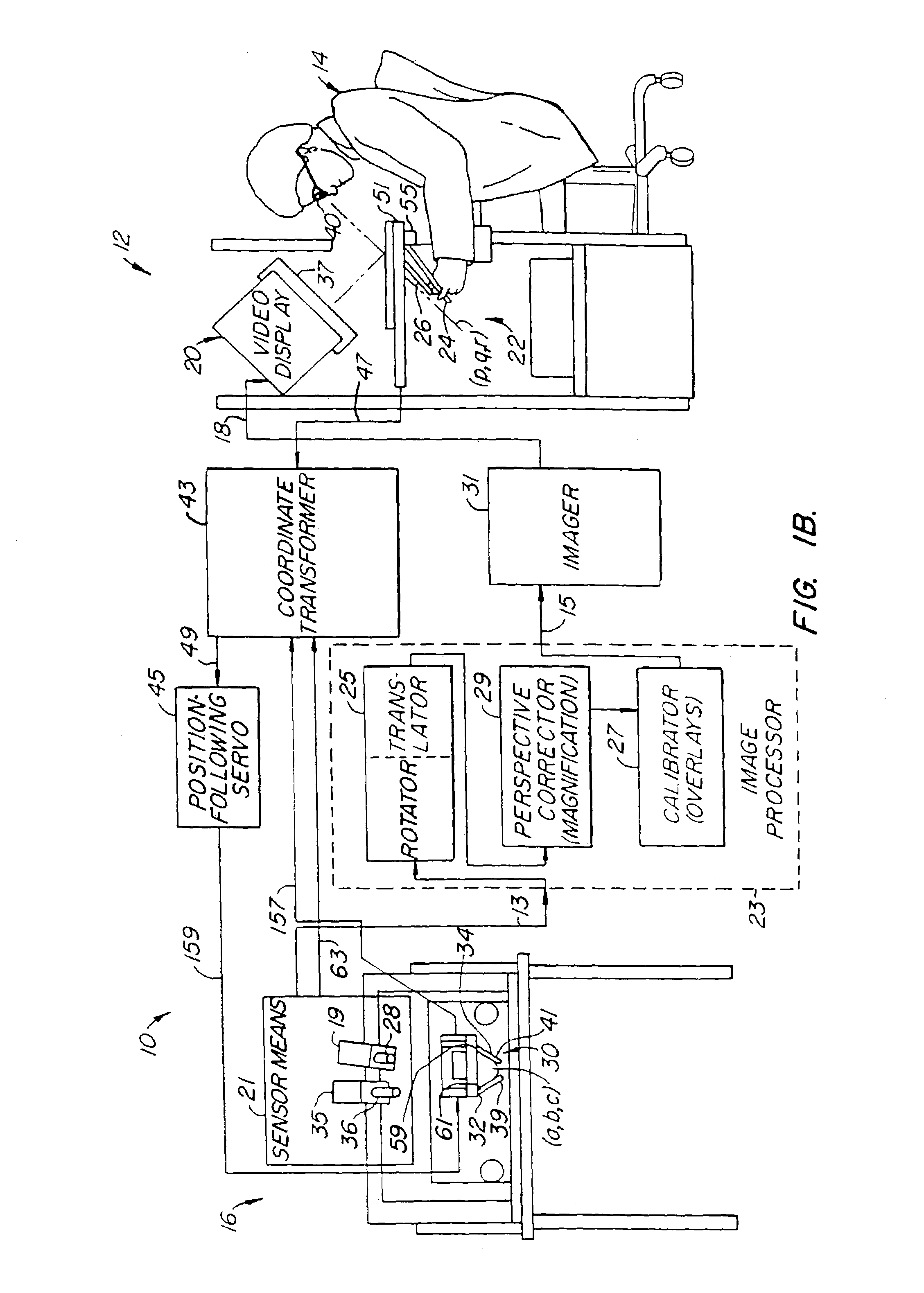
[0022]FIG. 1A shows a telemanipulation system 10 according to the present invention with a remote operator station 12 where an operator 14 (a surgeon, for example) can perform telemanipulation on an object at a worksite station 16. The remote station 12 includes a video display 20 for the operator 14 to view the worksite and an apparent workspace 22 where the operator 14 carries out the actual manipulations by grasping hand control means 24, 26, such as surgical instrument handles, which are connected to position sensors 51, 55. The worksite station 16 includes an image capture means 19, including a sensor means 21 with camera lens 28 of a camera or endoscope and understanding that there is an image capture means 19 associated with that lens, which captures an image of an object located in the workspace 30. (An endoscope would be within the body cavity.) The manipulators 32, 34 allow manipulation of the object in the workspace 30 correlated with a displayed image by use of end effec...


PUM

PropertyMeasurementUnit
angleaaaaaaaaaa
angleaaaaaaaaaa
angleaaaaaaaaaa

Abstract

In a telemanipulation system for manipulating objects located in a workspace at a remote worksite by an operator from an operator's station, such as in a remote surgical system, the remote worksite having a manipulator with an end effector for manipulating an object at the workspace, such as a body cavity, a controller including a hand control at the control operator's station for remote control of the manipulator, an image capture device, such as a camera, and image output device for reproducing a viewable real-time image, the improvement wherein a position sensor associated with the image capture device senses position relative to the end effector and a processor transforms the viewable real-time image into a perspective image with correlated manipulation of the end effector by the hand controller such that the operator can manipulate the end effector and the manipulator as if viewing the workspace in true presence. Image transformation according to the invention includes translation, rotation and perspective correction.

Description

CROSS-REFERENCES TO RELATED APPLICATIONS[0001]This application is a continuation of, and claims the benefit of priority from, U.S. patent application Ser. No. 09 / 813,506 filed Mar. 21, 2001, now U.S. Pat. No. 6,574,355 issued on Jun. 3, 2003; which is a continuation of U.S. patent application Ser. No. 09 / 174,051 filed Oct. 15, 1998, now U.S. Pat. No. 6,259,806 issued on Jul. 7, 2001; which is a continuation application of U.S. patent application Ser. No. 08 / 783,644, filed Jan. 14, 1997, now U.S. Pat. No 5,859,934 issued on Jan. 12, 1999, which is a continuation application of U.S. patent application Ser. No. 08 / 239,086 filed May 5, 1994, now U.S. Pat. No. 5,631,973 issued on May 20, 1997, the full disclosures of which are incorporated herein by reference. This application is also a continuation-in-part application of U.S. patent application Ser. No. 08 / 709,930 filed Sep. 9, 1996, now U.S. Pat. No. 6,963,792 issued on Nov. 8, 2005; which is a continuation of U.S. patent application S...

Claims


Application Information

Patent Timeline
Patent Type & Authority Patents(United States)
IPC IPC(8): G06K9/00A61B1/00A61B1/04B25J3/00A61B17/00A61B19/00B25J3/04B25J7/00B25J9/16B25J19/02B25J19/04B65B5/06B65B35/50B65B57/20B65B59/00G03C1/005G03C1/09G06T1/00G06T3/00G06T19/00H04N13/00
CPCA61B19/22A61B19/2203B25J3/04B25J9/1689B25J19/023G06T1/0014G06T3/00H04N13/0239H04N13/0246H04N13/0296H04N13/0434H04N13/0438H04N13/0497A61B17/00234A61B19/5212A61B2019/2223A61B2019/223A61B2019/2292G03C1/0053G05B2219/35506G05B2219/39389G05B2219/40158G05B2219/40161G05B2219/40169G05B2219/45123H04N13/0055H04N13/0059A61B34/70A61B90/361A61B34/30A61B34/37A61B34/35A61B34/76H04N13/337H04N13/341H04N13/194H04N13/189H04N13/246H04N13/296H04N13/239H04N13/398
Inventor GREEN, PHILIP S.
Owner SRI INTERNATIONAL
Why Eureka
Try Eureka