Clearance measurement system and method of operation

a measurement system and clearance technology, applied in the direction of distance measurement, mechanical measurement arrangement, instruments, etc., can solve the problems of ineffective in-service measurement, measurement that does not account for clearance changes, and limitations of capacitance-based measurement techniques

Active Publication Date: 2008-02-19
GE INFRASTRUCTURE TECH INT LLC
View PDF14 Cites 50 Cited by
  • Summary
  • Abstract
  • Description
  • Claims
  • Application Information

AI Technical Summary

Problems solved by technology

Unfortunately, existing capacitance-based measurement techniques are limited in that they yield a direct current voltage based measurements for measuring clearances between stationary and rotating structures that are continuous in the direction of rotation.
As a result, the measurements do not account for changes in the clearance due to changes in temperature of the components, electronic drifts in the gain, offset of the electronics, oxidation of the bucket tip, and other factors.
Unfortunately, these existing systems are ineffective for in-service measurements due to the noise and drift generated by changes in the geometry of the components, among other factors.
As the components become worn during service, the offline measurements become ineffective for in-service clearance control.

Method used


Image

  • Clearance measurement system and method of operation
  • Clearance measurement system and method of operation
  • Clearance measurement system and method of operation

Examples


example 1

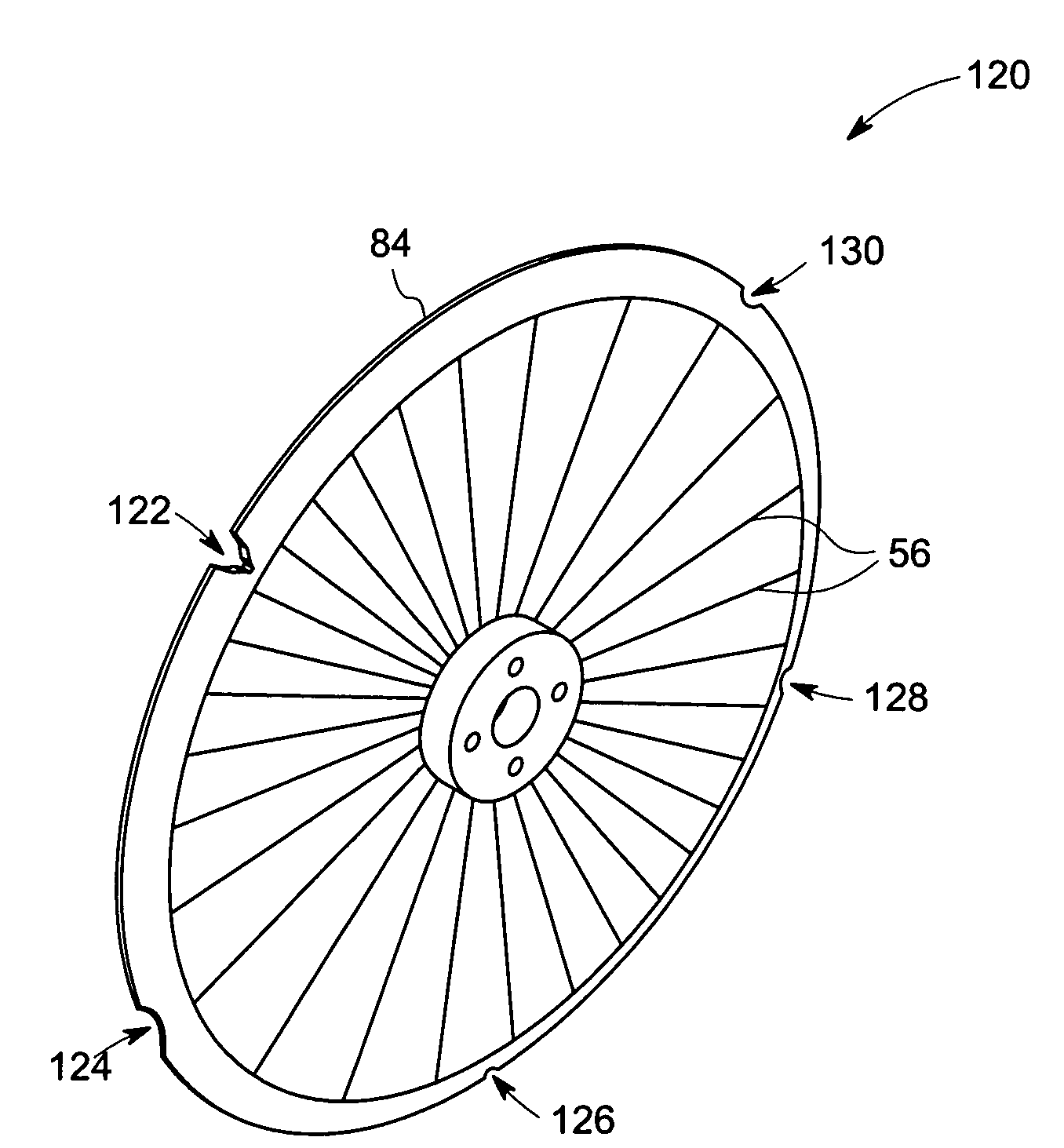
[0038]In an exemplary rotating machinery, the sensor output from the sensor 64 corresponding to the rotating component 82 at a distance “a” from the sensor 64 is represented by “x”. Further, the sensor output corresponding to the bottom of the reference geometry 86 (having a depth “b”) at a distance “a+b” is represented by “y”. Assuming that the clearance between the stationary and rotating components 62 and 82 changes to “2a” then the measurement from the sensor 64 corresponding to such clearance will be “x / 2”. In this embodiment, the bottom of the reference geometry 86 will be at a distance “2a+b” from the sensor 64. Therefore, the difference in signal corresponding to the rotating component 82 and the reference geometry 86 in the first case (at a distance a) will be “x−y”. Similarly, the difference in the signal for the second case (at a distance 2a) will be “x / 2−y”. Therefore, the difference between the two measurements is approximately x / 2 that corresponds to the clearance chan...


PUM


Abstract

A clearance measurement system is provided. The clearance measurement system includes a reference geometry disposed on a first object having an otherwise continuous surface geometry and a sensor disposed on a second object, wherein the sensor is configured to generate a first signal representative of a first sensed parameter from the first object and a second signal representative of a second sensed parameter from the reference geometry. The clearance measurement system also includes a processing unit configured to process the first and second signals to estimate a clearance between the first and second objects based upon a measurement difference between the first and second sensed parameters.

Description

BACKGROUND[0001]The invention relates generally to clearance measurement systems, and more particularly to a clearance measurement system for measuring a clearance between a stationary component and a continuous rotary component of a rotating machine.[0002]Various types of sensors have been used to measure the distance between two objects. In addition, these sensors have been used in various applications. For example, a steam turbine has a rotating bucket that is disposed adjacent a carrier. The clearance between the rotating bucket and the carrier varies due to various operating conditions, such as changes in temperature, oxidation of the bucket tip, and so forth. It is desirable that a gap or clearance between the rotating bucket and the carrier be maintained during operation of the steam turbine.[0003]One existing sensor is a capacitance probe, which measures a capacitance for estimating the clearance between two components. Unfortunately, existing capacitance-based measurement t...

Claims


Application Information

Patent Timeline
Patent Type & Authority Patents(United States)
IPC IPC(8): G01B5/14
CPCG01B7/144
Inventor ANDARAWIS, EMAD ANDARAWISBALASUBRAMANIAM, MAHADEVANANDERSON, TODD ALANDASGUPTA, SAMHITASHADDOCK, DAVID MULFORDMANI, SHOBHANAJIANG, JIE
Owner GE INFRASTRUCTURE TECH INT LLC
Why Eureka
Try Eureka