System and method for recovery units in databases

a database and recovery unit technology, applied in the field of computer databases, can solve the problems of database inaccessibility, database limit push, database bottleneck by limit,

Inactive Publication Date: 2008-02-19
MICROSOFT TECH LICENSING LLC
View PDF2 Cites 22 Cited by
  • Summary
  • Abstract
  • Description
  • Claims
  • Application Information

AI Technical Summary

Benefits of technology

[0005]The construction of multiple recoverable database partitions called recovery units in a database is useful for adding the capability to perform maintenance or disaster recovery on only one portion of a database while allowing other portions to be accessible. This may be especially useful in very large databases where the bottleneck of a single log stream or log stream coordination mechanism may slow down recovery operations. The method involves partitioning the database into multiple recovery units and creating a primary and secondary catalog of metadata.
[0007]After the primary and secondary catalogs are defined, the primary and secondary catalog are linked and a recovery unit may be exercised to perform maintenance or recovery operation on only one portion or recovery unit of the database while the other recovery units are accessible to users of the database. In one embodiment of the invention, a recovery unit may be used to copy one portion of a database to another thereby extending its utility beyond recovery purposes.

Problems solved by technology

Maintenance or disaster recovery schemes render the database unavailable during the time of maintenance or recovery.
The log stream becomes a bottleneck that leads to significant manageability and performance issues that increasingly push the limits of the hardware the databases reside upon.
Eventually, the database becomes bottlenecked by the limits of the single log stream and its accessibility and speed with regard to recovering database information.
However, as this solves the problem of bottlenecking of the log stream data, it generates another problem in that the coordination mechanism 205 is eventually subject to slowness as the size of the database grows.
Although the architecture of FIG. 2 is an improvement of that of FIG. 1, it still has limiting speed performance due to the bottleneck of the coordination mechanism 205 and the entire database is still unavailable during a recovery operation involving the log data streams.

Method used


Image

  • System and method for recovery units in databases
  • System and method for recovery units in databases
  • System and method for recovery units in databases

Examples


Embodiment Construction

Overview

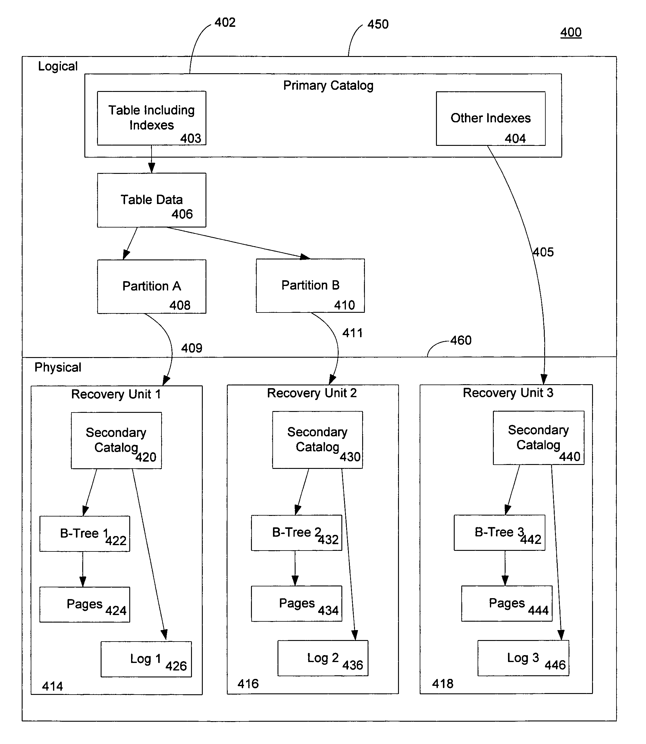
[0017]An embodiment of the invention provides for multiple recovery units in a database that allows for addressing the bottleneck problems of the prior art and additionally provides the capability to increase overall database availability. This may be accomplished by having only parts of the database be unavailable during maintenance or disaster recovery scenarios. One aspect of invention provides for separation of metadata between logical elements of the database and physical elements. The logical elements include the database, tables, indexes, partitions of tables and indexes, data types, constraints, stored procedures, triggers, and filegroups that the user sees. The physical elements include the pages, files, B-trees, heaps, recovery units, and log which are invisible to the end user. Metadata representing the logical elements of the database are stored in a “primary” recovery unit, while the metadata for the physical elements of a database are stored in their own respec...


PUM


Abstract

The creation of multiple recoverable units within a database allows a database partition to be reconstructed during maintenance and disaster recovery operations. A method of creating a recovery unit includes partitioning a database into at least two recovery units. A primary catalog of metadata relating to the logical elements of a database such as tables, indexes, and file groups is created. A secondary catalog of metadata relating to the physical elements of a database such as pages, files, B-Trees, and log streams is created for each recovery unit. The primary and secondary metadata catalogs are linked such that only one log stream is associated with any one recovery unit. A single recovery unit may then be exercised to perform recovery or maintenance operations while the remaining recovery units of the database remain online.

Description

FIELD OF THE INVENTION[0001]This invention relates in general to the field of computer databases. More particularly, this invention relates to the use of multiple independent recoverable units in a database structure.BACKGROUND OF THE INVENTION[0002]Most modern databases exhibit the characteristic of being either totally available or totally unavailable. Maintenance or disaster recovery schemes render the database unavailable during the time of maintenance or recovery. The unit of availability in such a scheme is the entire database. FIG. 1 depicts a prior art database 100, partitioned into tables A, B, and C, 101, 102, and 103 respectively. Each table uses a single log stream, 105, to log changes in row and other data to keep the database transactionally consistent. As the size of the database increases and as more tables are added to the database, a greater amount of data must be written to the log stream, 105. The log stream becomes a bottleneck that leads to significant manageab...

Claims


Application Information

Patent Timeline
Patent Type & Authority Patents(United States)
IPC IPC(8): G06F17/30
CPCG06F11/1471G06F2201/80Y10S707/99953G06F11/1469G06F17/40
Inventor BYRNE, PETER
Owner MICROSOFT TECH LICENSING LLC
Why Eureka
Try Eureka