Power toothbrush

a toothbrush and power technology, applied in the field of power toothbrushes, can solve the problems of uneven stroke and frequency of reciprocal motion or rolling motion of the toothbrush, and the inability of conventional toothbrushes to effectively remove the dirt in the interdental portion of the teeth, and achieve the effect of effectively removing the dir

Inactive Publication Date: 2008-02-26
MATSUSHITA ELECTRIC WORKS LTD
View PDF13 Cites 22 Cited by
  • Summary
  • Abstract
  • Description
  • Claims
  • Application Information

AI Technical Summary

Benefits of technology

[0007]By such a configuration, when the top ends of the brush staples are contacted on surfaces of the teeth along the convex and concave shapes of the teeth, and the brush base portion is driven by a predetermined stroke or a predetermined swing angle and a predetermined frequency or predetermined rolling speed, the dirt or plaque remained in the interdental portion of the teeth can be removed effectively.

Problems solved by technology

Stroke and frequency of the reciprocal motion or the rolling motion of the toothbrush, however, become uneven.
As a result, the conventional toothbrush cannot remove the dirt in the interdental portion of the teeth effectively.

Method used


Image

  • Power toothbrush
  • Power toothbrush
  • Power toothbrush

Examples


first embodiment

[0028]A first embodiment of the present invention is described with reference to FIGS. 1, 2, 3A, 3B and 4.

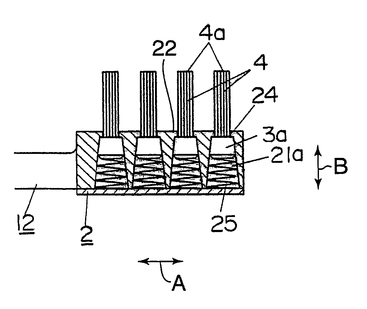
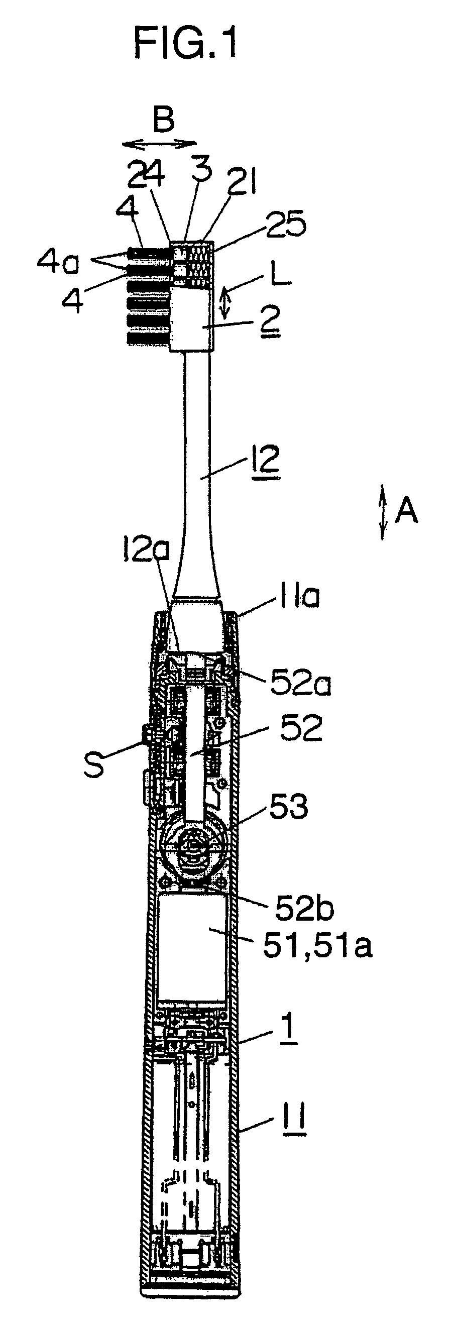
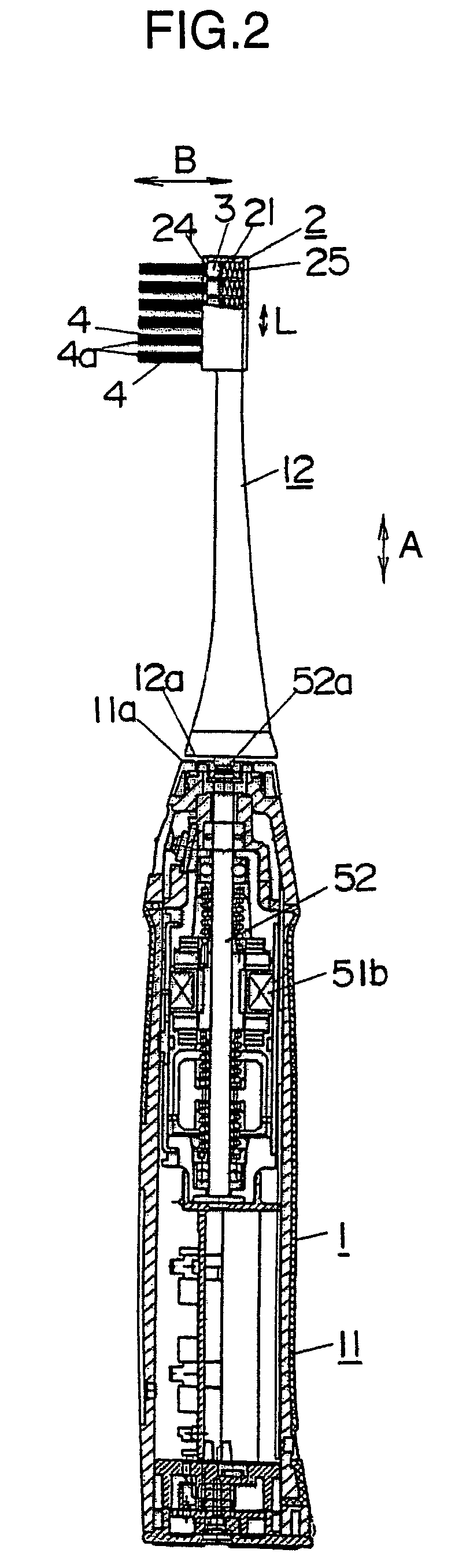
[0029]As can be seen from FIG. 1, a main body 11 having a shank shape and a brush attachment 12 configure a power toothbrush 1. The brush attachment 12 is detachably engaged with the main body 11. A brush base portion 2 is formed at a top end of the brush attachment 12. A plurality of floating base members 3 is floatingly provided in the brush base portion 2 of the brush attachment 12. A brush staple 4 is planted on each floating base member 3. A portion in the vicinity of a bottom end of the main body 11 serves as a grip of the power toothbrush 1.

[0030]An actuator 51 such as an electric motor and the driving shaft 52 for transmitting driving force of the actuator 51 to the brush attachment 12 are provided in the main body 11. A switch “S” whish will be used for switching on and off of the actuator 51 and for selecting the driving state of the actuator 51 is provided on a surfac...

second embodiment

[0053]A second embodiment of the present invention is described with reference to FIGS. 8A to 8D, 9 and 10, 11A to 11C, 12A and 12B.

[0054]In comparison with the above-mentioned first embodiment, brush staples 40b are directly planted on the brush base portion 2 of the brush attachment surrounding brush staples 40a planted on the floating base member 3. Two brush staples 40a are planted on each floating base member 3, and each floating base member 3 is floatingly supported by a single spring 25. The brush staples 40a are fitted into planting holes 30 formed on the floating base member 3. Both sides of the floating base members 3 are tapered, while the sidewalls of the guiding hollows 21 are not tapered. A boss 32, with which the top end of the spring 25 such as a coil spring is engaged, is formed on the bottom face of the floating base member 3. A spot facing 27, to which the bottom end of the spring 25 is inserted, is formed on the bottom face 26 of the guiding hollow 21.

[0055]In th...


PUM


Abstract

In a power toothbrush, a brush base portion is provided at a top end of a brush attachment which is detachably engaged with a main body containing an actuator generating driving force for driving at least the brush base portion. The brush base portion can be reciprocally moved in an axial direction of the main body with a predetermined stroke and a predetermined frequency, swing around a rotation axis perpendicular to the axial direction of the main body with a predetermined swing angle and a predetermined frequency, or rotated around the rotation axis with a predetermined rotation speed. A plurality of floating base member is floatingly supported in guiding hollows formed in the brush base portion, and a brush staple is planted on each floating base member. Thus, dirt or plaque remained in interdental portion of the tooth can effectively be removed, when top ends of the brush staples contact the surfaces of the tooth.

Description

TECHNICAL FIELD[0001]The present invention relates to a power toothbrush in which at least a brush base portion of a brush attachment is driven by an actuator with respect to a main body thereof, and especially brush staples are floatingly movable with respect to the brush attachment.BACKGROUND ART[0002]Conventional toothbrushes, in which brush staples are floatingly movable with respect to brush base portion, are described in, for example, Publication Gazette of Japanese Patent Application 5-123218 shown in FIG. 13 and Publication Gazette of Japanese Patent Application 7-265127 shown in FIG. 14. In the conventional toothbrushes which are not the power toothbrush, a brush base portion 2′ is formed in the vicinity of a top end opposite to a grip portion of a main body the toothbrush. A plurality of floating bases 3 is floatingly provided in the brush base portion 2′, and a blush staple 4 is planted on each floating base 3.[0003]In the conventional toothbrush, the brush staples 4 are ...

Claims


Application Information

Patent Timeline
Patent Type & Authority Patents(United States)
IPC IPC(8): A46B7/08A46B9/10A46B3/00A46B7/06A46B9/04A46B9/08A61C17/00A61C17/22A61C17/34
CPCA46B7/06A46B9/026A46B9/08A61C17/3436A61C17/3445A46B2200/1066A46B13/02
Inventor KUNITA, TOMOHIROTANIGUCHI, SHINICHI
Owner MATSUSHITA ELECTRIC WORKS LTD
Why Eureka
Try Eureka