Method for making a hollow fan blade with machined internal cavities
a hollow fan blade and internal cavity technology, applied in the field of gas turbine engines, can solve the problems of increasing time and cost of operation, reducing reducing the durability of the skin, so as to reduce the number of internal cavities, reduce weight and cost, and improve durability
- Summary
- Abstract
- Description
- Claims
- Application Information
AI Technical Summary
Benefits of technology
Problems solved by technology
Method used
Image
Examples
first embodiment
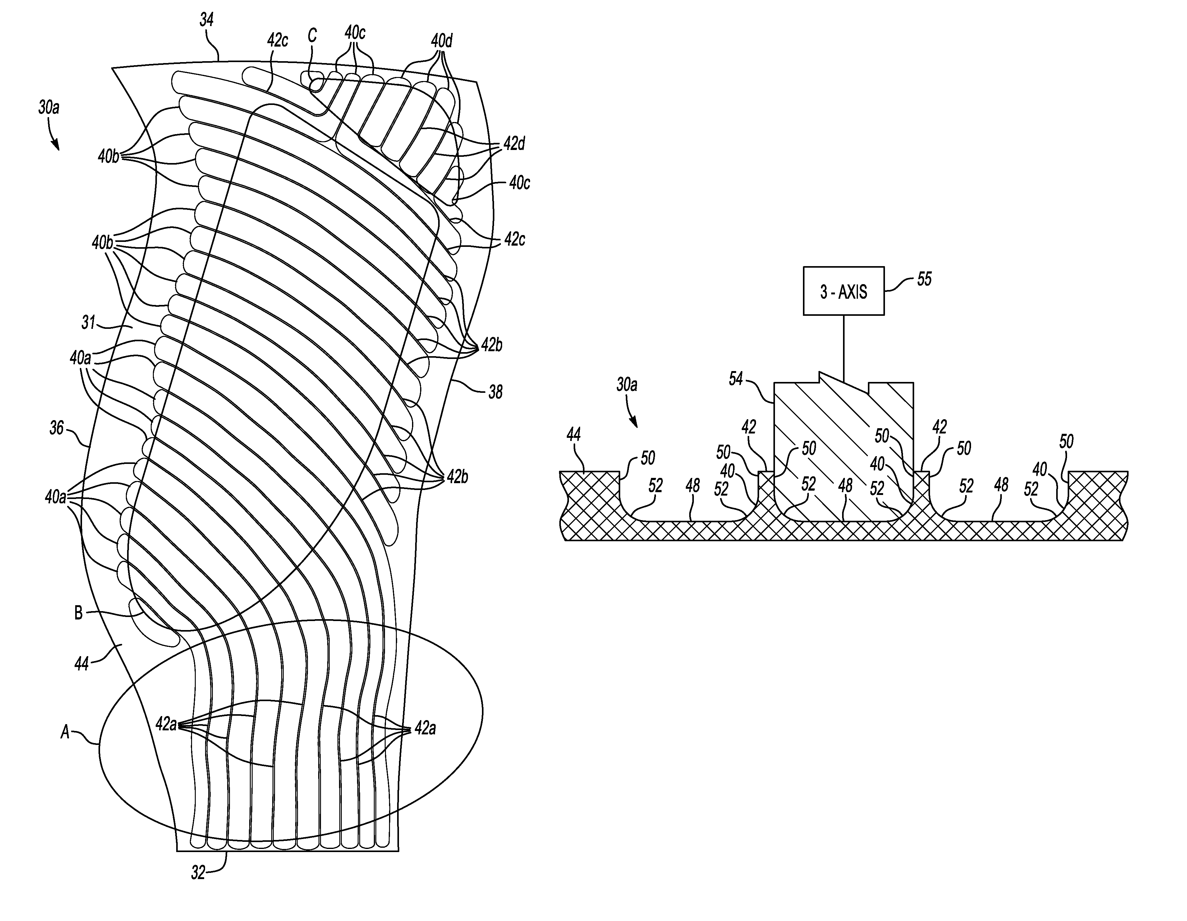
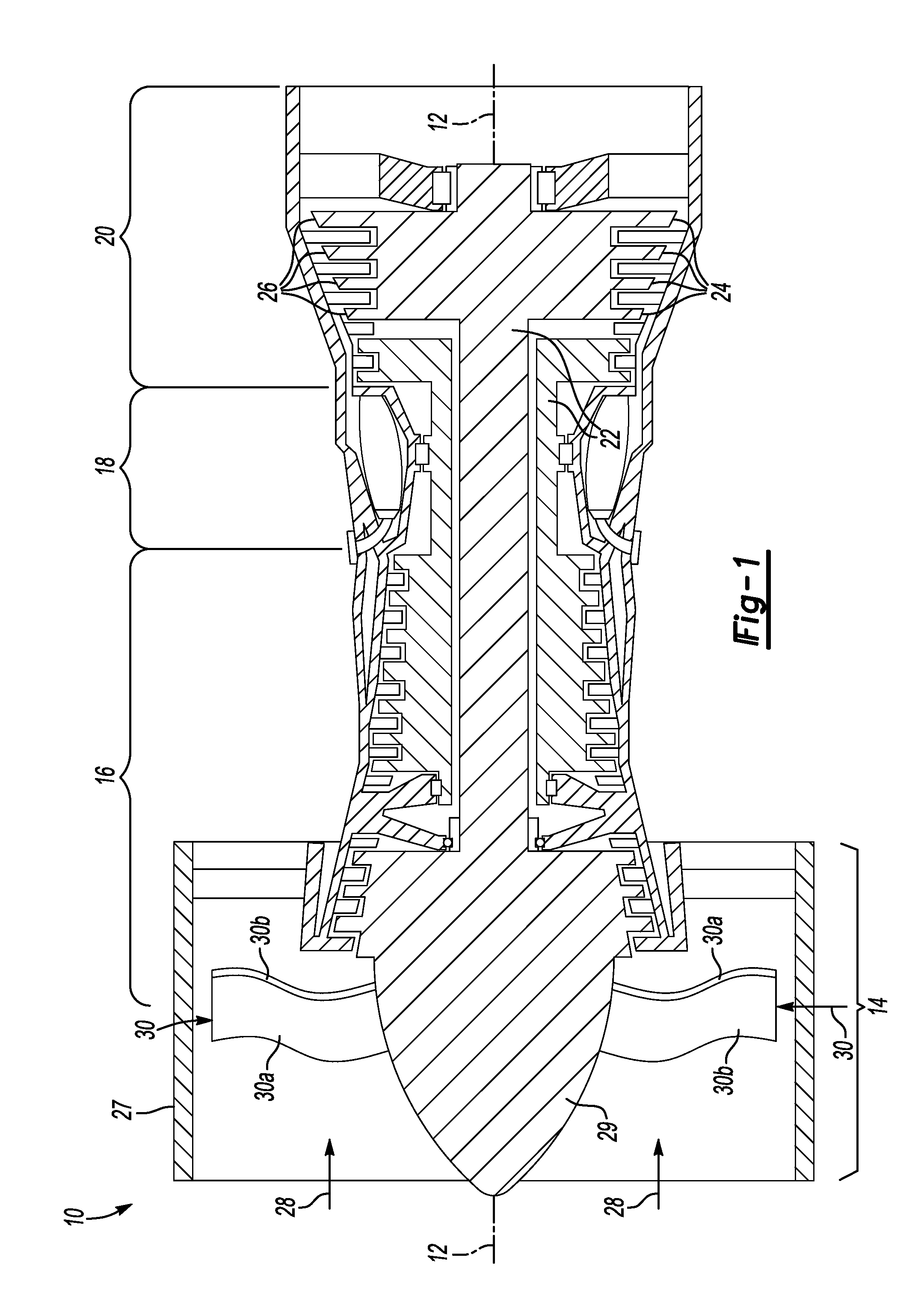
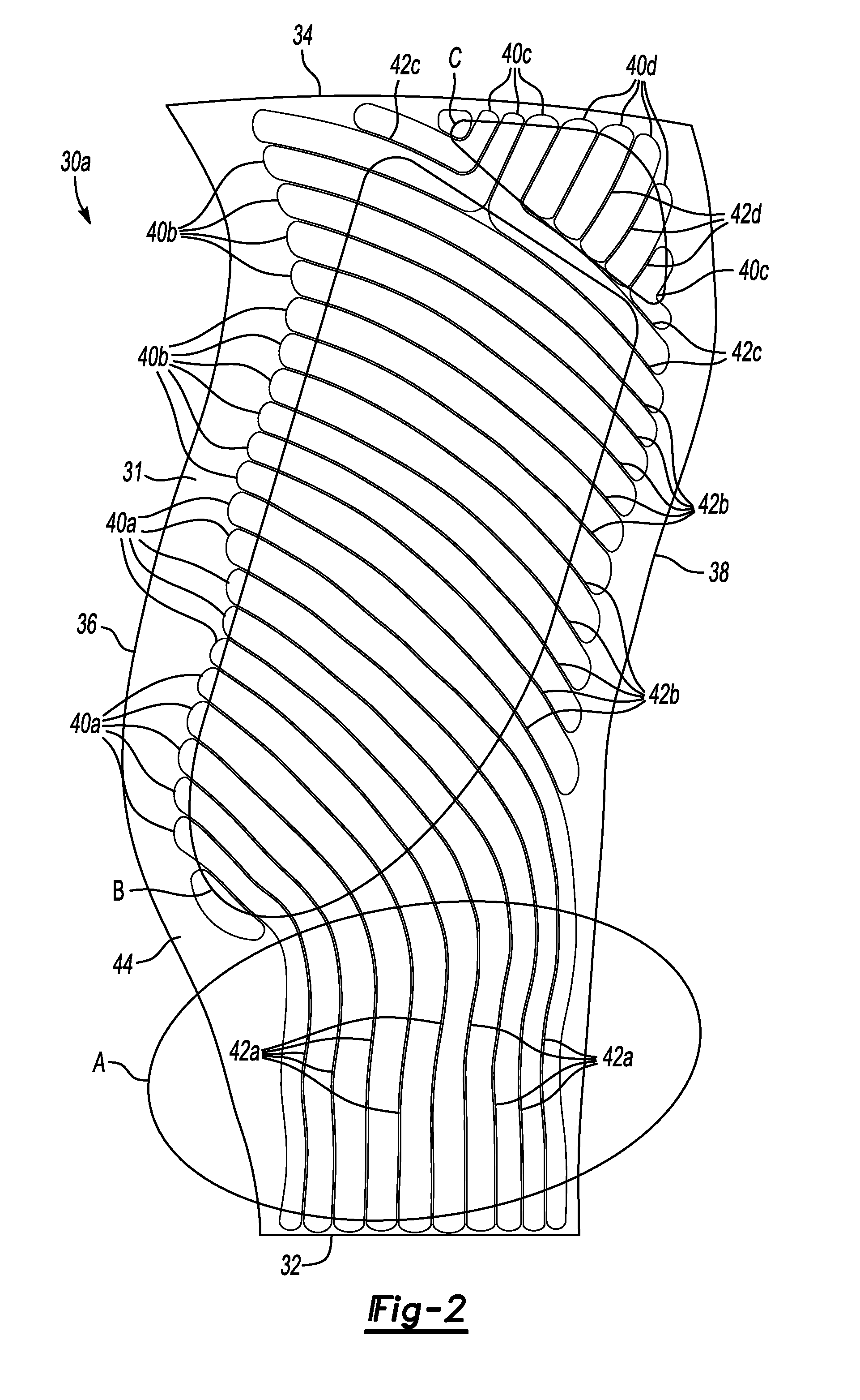
[0025]one fan blade detail half 30a is shown in FIG. 2. The other fan blade detail half 30b would be complementary. The fan blade detail half 30a comprises a substrate 31, preferably Titanium, having a root edge 32 opposite a tip 34 and a leading edge 36 opposite a trailing edge 38. The fan blade detail half 30a includes Region A, which is approximately the radially inner-most third adjacent the root edge 32. Region B extends from Region A toward the tip 34, excluding a corner area adjacent the tip 34 and trailing edge 38, which is Region C.
[0026]In order to reduce weight while still maintaining the necessary stiffness and strength, a plurality of elongated continuous cavities 40a-d are machined into the interior surface of the substrate 31. The cavities 40a-d are spaced from one another to form a plurality of continuous, non-intersecting ribs 42a-d. Alternatively (or additionally), the ribs 42a-d are superplastically formed. Throughout this description, the reference numeral 40 may...
second embodiment
[0038]FIG. 10 illustrates a fan blade detail half 60a that could be used in the turbine engine 10 of FIG. 1. Again, the other fan blade detail half (not shown) would be complementary. The fan blade detail half 60a comprises a substrate 61, preferably Titanium, having a root edge 62 opposite a tip 64 and a leading edge 66 opposite a trailing edge 68. A plurality of elongated continuous cavities 70 are machined into or superplastically or otherwise formed on the interior surface of the substrate 61 in the manner described above with respect to FIGS. 3 and 4. The cavities 70 are spaced from one another to form a plurality of continuous non-intersecting ribs 72, 73. In this embodiment the spacing between ribs is held constant throughout.
[0039]In the second embodiment, the cavities 70a-d extend continuously alongside ribs 72a-e and ribs 73. The cavities 70a-d also extend around freestanding ends 74 of some of the ribs 72a-e, thereby reducing the number of cavities 70a-d.
[0040]The fan bl...
PUM
| Property | Measurement | Unit |
|---|---|---|
| degree angle | aaaaa | aaaaa |
| angle | aaaaa | aaaaa |
| angle | aaaaa | aaaaa |
Abstract
Description
Claims
Application Information
 - R&D
- Intellectual Property
- Life Sciences
- Materials
- Tech Scout
- Unparalleled Data Quality
- Higher Quality Content
- 60% Fewer Hallucinations
Browse by: Latest US Patents, China's latest patents, Technical Efficacy Thesaurus, Application Domain, Technology Topic, Popular Technical Reports.
© 2025 PatSnap. All rights reserved.Legal|Privacy policy|Modern Slavery Act Transparency Statement|Sitemap|About US| Contact US: help@patsnap.com


