
Method of manufacturing cylindrical bearing member
a technology of cylindrical bearings and bearing parts, which is applied in the direction of sliding contact bearings, mechanical equipment, transportation and packaging, etc., can solve the problems of deterioration of lubricating properties, poor oil reserve efficiency, and inability to hold lubricating oil for a long time, so as to improve oil reserving efficiency and efficient formation
- Summary
- Abstract
- Description
- Claims
- Application Information
AI Technical Summary
Benefits of technology
Problems solved by technology
Method used
Image

Examples
Embodiment Construction
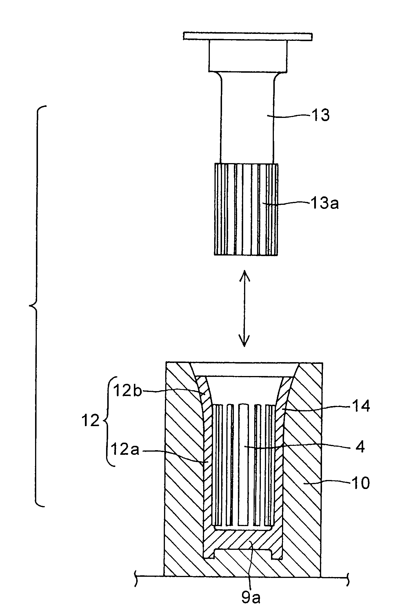
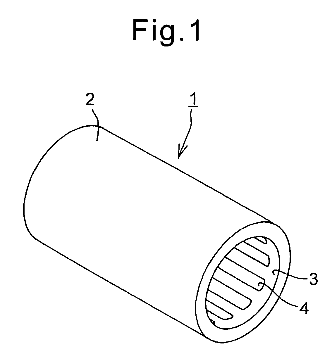
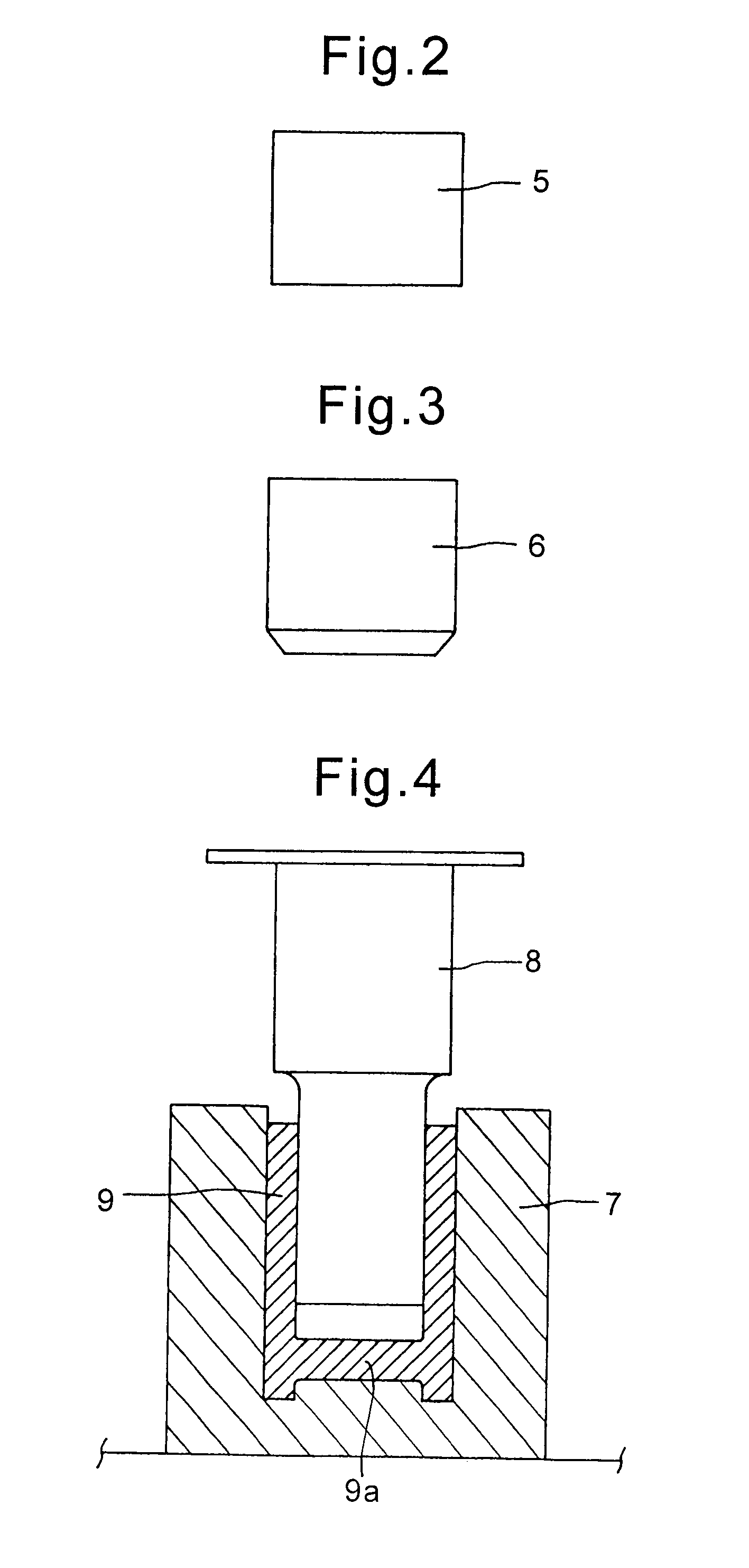
[0029]A cylindrical bearing member made in accordance with the present invention is illustrated in FIGS. 1 and 8. The bearing member 1 is a hollow cylinder 2 having an inner circumferential surface 3. The interior surface 3 is provided with a plurality of blind grooves 4 parallel to the axial direction of the hollow cylindrical portion 2. As shown in FIG. 8, the blind grooves 4 are formed in the central portion 3c of the inner cylindrical surface of the cylindrical portion 2. The opposite ends of the central body portion 3c are spaced from the open ends of the bearing member 1 to form top portion 3a and bottom portion 3b. The blind grooves 4 are confined to the central body portion 3c and terminate in blocked ends 4a and 4b which are spaced inwardly from the open ends of the cylindrical member 1 so that the end portions 3a and 3b of the inner cylindrical surface are provided with a continuous uninterrupted surface. The spacing from the open ends is preferably greater than the thickn...
PUM
| Property | Measurement | Unit |
|---|---|---|
| axial length | aaaaa | aaaaa |
| size | aaaaa | aaaaa |
| length | aaaaa | aaaaa |
Abstract
Description
Claims
Application Information