Priming apparatus for a centrifugal pump

a centrifugal pump and priming technology, applied in the field of priming apparatuses for centrifugal pumps, can solve the problems of unsatisfactory prior efforts, easy damage, and undesirable pumpage to enter the vacuum system, and achieve the effects of reducing the incidence of surging and turbulence, and reducing the abrupt change of fluid level in the hopper

Inactive Publication Date: 2008-02-26
GORMAN RUPP COMPANY THE
View PDF29 Cites 17 Cited by
  • Summary
  • Abstract
  • Description
  • Claims
  • Application Information

AI Technical Summary

Benefits of technology

[0013]In a more preferred embodiment, the valve member is located within a valve chamber that forms part of the housing. The valve chamber fully encloses the valve member and associated sealing elements. The interior of the valve chamber communicates with the hopper through cross passages formed in the walls of the valve chamber. According to this preferred embodiment, the valve chamber wall defines a splash shield located below the cross passages. The splash shield includes transversely extending structure which inhibits fluid carryover from the hopper into the valve chamber.
[0016]According to still another feature of the invention, a baffle is located at an inlet to the hopper and is operative to reduce surging and turbulence in the hopper. The baffle includes a support plate that defines openings that communicate the inlet of the pump with the hopper. A spider-like flow diverter overlies the openings in the support plate. The flow diverter has downwardly depending tabs that are attached to the support plate which, together with the support plate, define transverse openings through which fluid from the pump inlet must flow in order to enter the hopper. The circuitous path that defined by the baffle reduces the incidence of surging and turbulence in the hopper. It also reduces abrupt changes in fluid level in the hopper.

Problems solved by technology

It should be apparent that it is undesirable for the pumpage to enter the vacuum system (often termed “carry over”).
When a vacuum pump is used as a source of vacuum, it is easily damaged if the liquid being pumped, even if water, enters the pump.
It is believed that these prior efforts have not been entirely satisfactory.
In actual operation, it has been found that surges occur in the fluid being pumped which cause abrupt changes in liquid level in the priming chamber.
This adds unwanted expense to the pumping systems.

Method used


Image

  • Priming apparatus for a centrifugal pump
  • Priming apparatus for a centrifugal pump
  • Priming apparatus for a centrifugal pump

Examples


Embodiment Construction

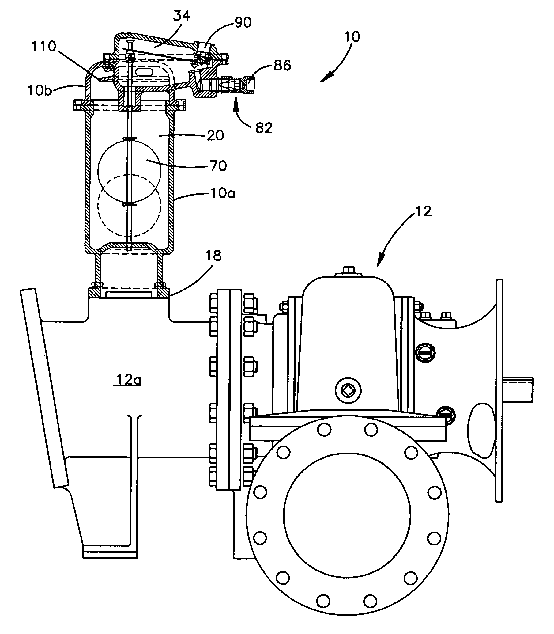
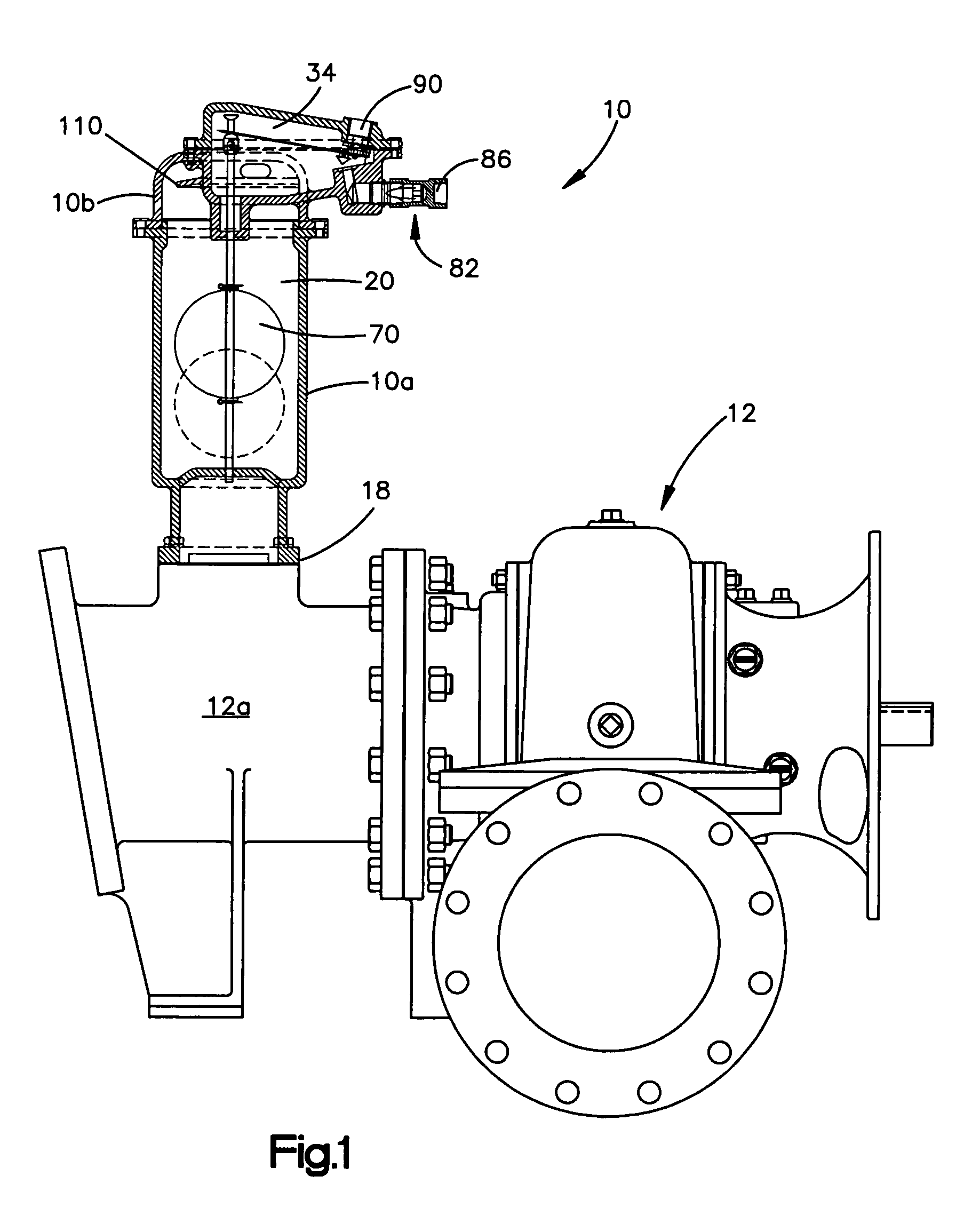
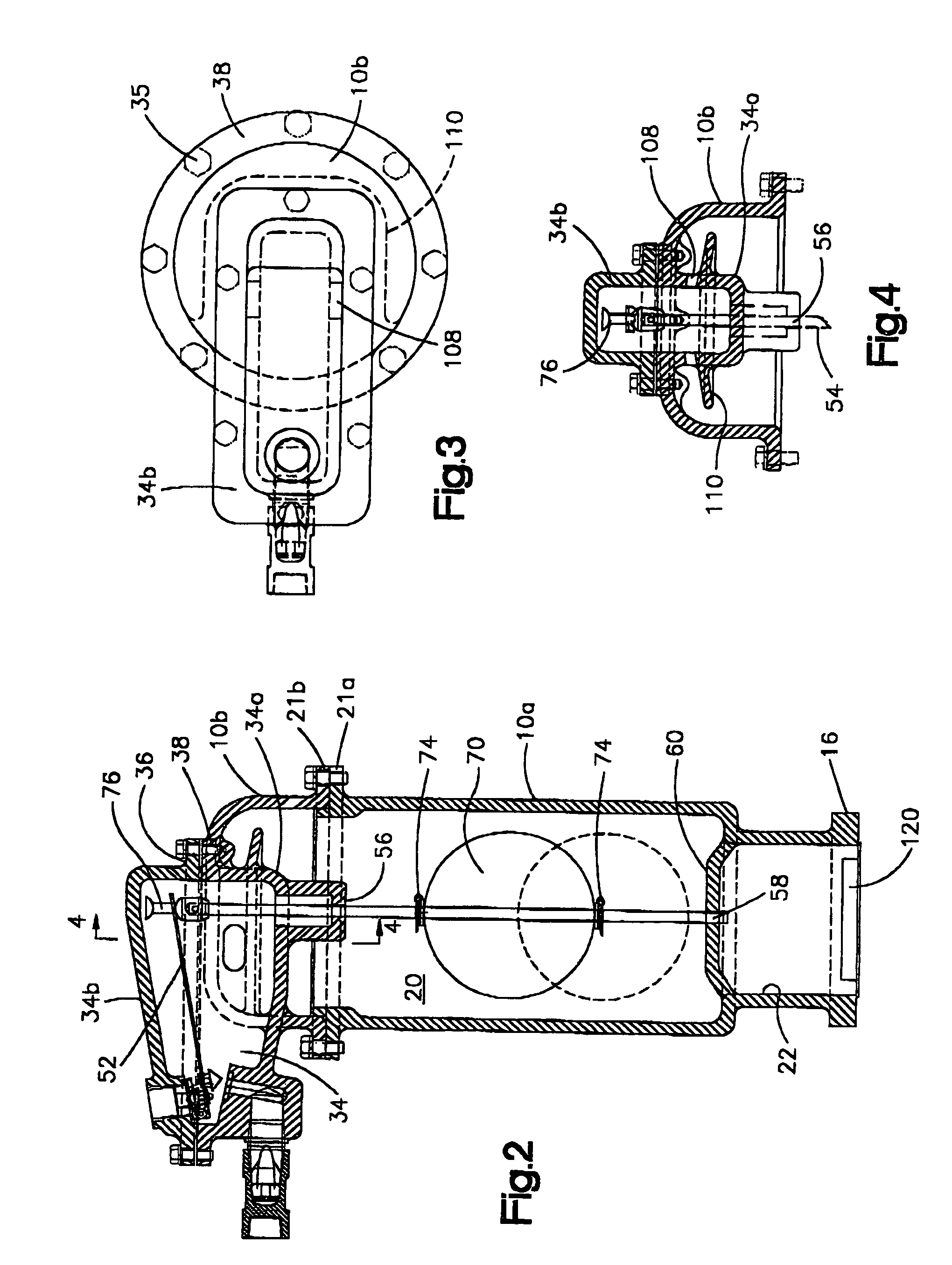
[0026]FIG. 1 shows the overall construction of a vacuum assisted priming unit 10 embodying the present invention. In the preferred and illustrated embodiment, the priming unit 10 is self contained and is attachable to the suction inlet 12a of a pump, such as a centrifugal pump 12. Referring also to FIG. 2, the unit 10 includes a mounting flange 16 defining a plurality of mounting holes. The flange 16 is bolted to a mating flange 18 on the pump 12 which typically forms part of the pump inlet 10. Other mounting arrangements, however, are contemplated by the present invention. Accordingly, this invention should not be limited to one in which mating flanges are used to mount the apparatus, nor should the invention be limited to the illustrated mounting configuration and the location of the priming unit 10.

[0027]The priming unit 10 includes upper and lower housing members 10a, 10b having respective mating flanges 21a,21b that are bolted together. The housing member 10a defines a float ch...


PUM


Abstract

A vacuum assisted priming system for a fluid pump including a housing defining a hopper that communicates with a pump inlet. The housing mounts a first port that communicates with the source of vacuum and a second port that communicates with atmosphere. A check valve allows atmospheric air to flow into the housing under certain operating conditions but inhibits reverse flow. A valve member pivotally mounted within a valve chamber carries first and second sealing elements that are engageable with first and second seats. The lever arm is operatively connected to a float via a lost motion connection. When the fluid level in the hopper rises to a predetermined level, an actuating rod moves the lever arm to a first sealing position. When the fluid level falls to a predetermined level, the actuating rod moves the lever arm to a second sealing position. A baffle located at an inlet to the hopper reduces surging and turbulence in the hopper and defines a circuitous path through which the fluid must flow in order to enter the hopper.

Description

TECHNICAL FIELD[0001]The present invention relates generally to pumps and, in particular, to pumps which use a vacuum source to aid or effect priming of the pump at start-up and / or to maintain the prime of the pump during its operation.BACKGROUND ART[0002]For at least some pumping applications which employ centrifugal pumps, a vacuum source connected at or near the inlet of the pump is used to aid or effect priming of the pump at start-up or to maintain the priming of the pump during its operation. One application of this type of centrifugal pump is in the pumping of sewage.[0003]There are several methods for creating a source of vacuum for the centrifugal pump. One method utilizes an “eductor” which those skilled in the art will recognize as a device which uses high pressure air flowing through a venturi to create a source of vacuum. Another method of providing the required vacuum is the use of a vacuum pump. To effect priming of a pump, the vacuum source is placed in fluid communi...

Claims


Application Information

Patent Timeline
Patent Type & Authority Patents(United States)
IPC IPC(8): F16K33/00F04B23/08F04D9/04F04F3/00F16K11/14F16K27/00
CPCF16K11/14F16K27/003Y10T137/74Y10T137/7365Y10T137/87016Y10T137/7485Y10T137/3087Y10T137/3099
Inventor SCOTT, THOMAS M.
Owner GORMAN RUPP COMPANY THE
Why Eureka
Try Eureka