Fixing device

a fixing device and a technology for fixing rods, applied in the direction of hose connections, couplings, rod connections, etc., can solve the problems of difficult modification, too expensive from the technical viewpoint to apply for simple fixing purposes, and complicated interlocking process introduction and mounting, so as to achieve easy assembly and safe operation

Inactive Publication Date: 2008-02-26
HYDAC ACCESSORIES
View PDF12 Cites 4 Cited by
  • Summary
  • Abstract
  • Description
  • Claims
  • Application Information

AI Technical Summary

Benefits of technology

[0007]Objects of the present invention are to provide a fastening device with a small number of components, one which may be added directly to a clamp as a supplement, and which can perform a wide range of fastening tasks and is easy to assemble and safe to operate.
[0009]Introduction of the retaining means into the respective mounting loop facilitated by the semicircular shapes of the retaining elements and their insertion bevels. That the fastening process not only is immediately clear to an assembler, but also the respective assembly and if necessary disassembly process is so easy that the necessary steps may be taken in rapid sequence for a plurality of lug connections without the possibility of occurrence of disruptive interlocking or the like. In the aggregate, this design results in distinctly improved handling of the fastening device. Any faulty assembly is also eliminated in this way. In addition, the lug strip may be loosened immediately after removal of the retaining means, while the retaining means may also remain at the fastening site. However, it is also possible, of course, to introduce the fastening device as a whole, as assembled, immediately at the factory. The fastening device of the present invention has proved to be suitable in particular for use in the motor vehicle industry, for example, when it is necessary securely to fasten air filters subject to vibration or the like within a vehicle.
[0010]In one preferred embodiment of the fastening device of the present invention, the mounting opening of the respective mounting loop extends along the longitudinal axis of the lug strip. The mounting opening has at least two component areas with different opening cross-sections. The component area with the larger opening cross-section is used for introduction of the restraining means. The other component area with the smaller opening cross-section is for passage of the operating element when the retaining means has been fully introduced into the mounting loop. As a result, simplicity of introduction of the respective retaining means into the associated mounting loop is ensured, while with the retaining means introduced, if the operating element passes through the component area with the smaller cross-section, cannot unintentionally fall from the mounting loop, something which definitely facilitates assembly and handling of the fastening device of the present invention.
[0011]In another preferred embodiment of the fastening device of the present invention, in addition to the two component areas, a third component area is present and is in the form of a slot with a further reduced opening cross-section that adjoins the second component area and forms a stop for the operating element. Forces acting on the mounting loop, such as ones in the form of vibration forces, can be reliably diverted to the lug strip. Although the clamp structure is naturally weakened by the slot, a higher level of stability is thereby reached. Since the slot additionally forms a stop for the operating element, subsequent automatic assumption by the lug strip, after its installation, of the proper associated operating position relative to the operating element of the respective retaining means is ensured.
[0013]Preferably, provision is also made such that the enclosing elements of the respective mounting loop are provided with a convex curvature to form contact surfaces which correspond to the convex curvature of the retaining surfaces when the retaining means have been fixed in position. Adaptation of the convex curvature of contact surfaces to retaining surfaces ensures reliable contact, along with the desired diversion of forces into the lug strip, when the retaining means has been fixed in position.

Problems solved by technology

Because of the large number of operating elements and their assembly at the place of production, the disclosed solution is also relatively cost-intensive, so that it is too expensive from the technical viewpoint to apply for simple fastening purposes.
This interlocking correspondingly complicates the process of introduction and mounting.
Should the disclosed clamp design be modified for other application purposes within the range of its operating elements, such modification can be accomplished only with difficulty because of the selected connections between lug strip and operating element.

Method used


Image

  • Fixing device
  • Fixing device
  • Fixing device

Examples


Embodiment Construction

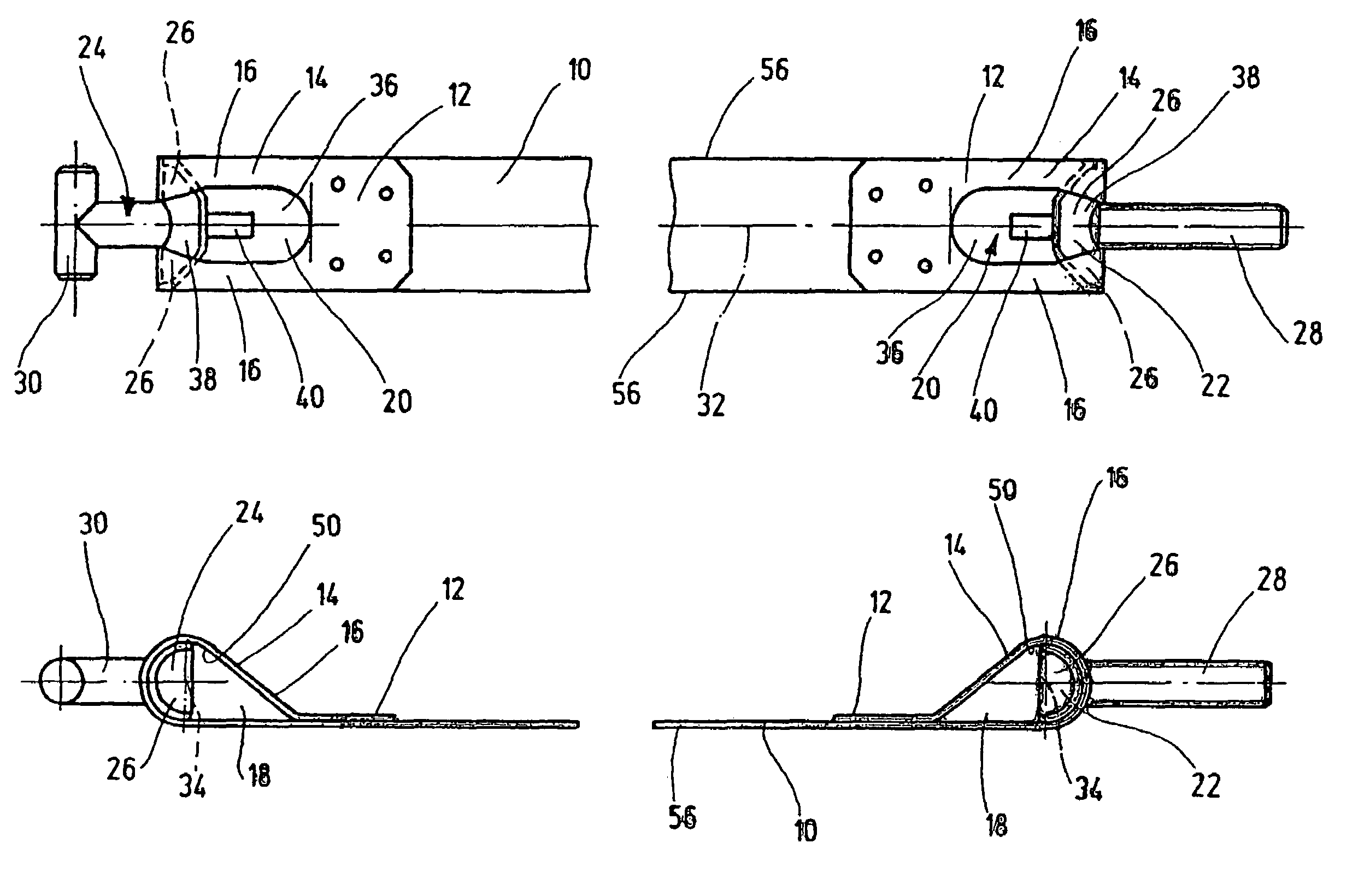
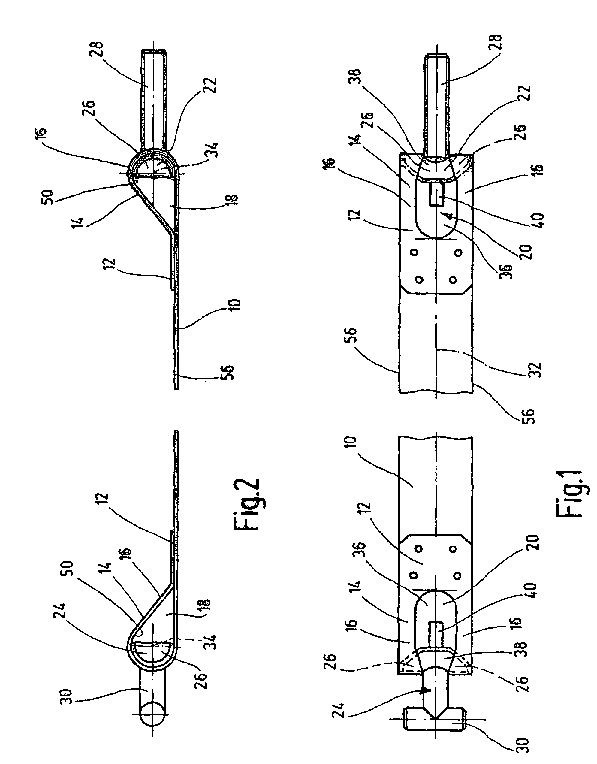
[0022]As is to be seen in FIGS. 1 and 2, the fastening device has a one-piece flexible lug strip 10. The length and width of the lug strip 10 may be predetermined. The two free ends 12 of the lug strip are bent, with each end forming a mounting loop 14. Each mounting loop 14 is bounded laterally by two enclosing elements 16 which enclose a mounting space 18. Between the enclosing elements a mounting opening 20 is delimited connecting the mounting space 18 to the exterior.

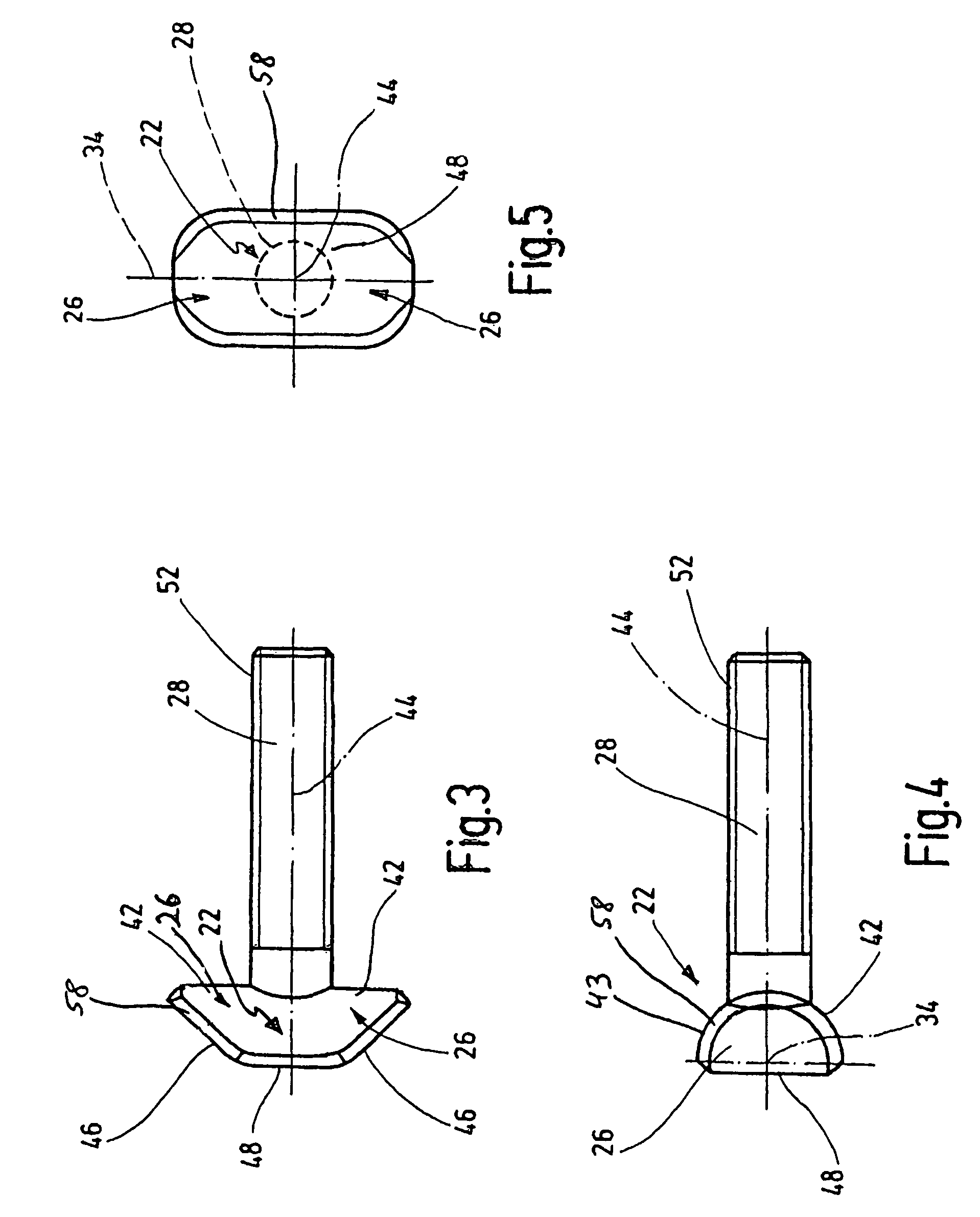
[0023]Retaining means 22, 24 may be introduced into the two mounting spaces 18. Each retaining means 22, 24 has two diametrically opposite retaining elements 26 for contacting the two enclosing elements 16, as well as an operating element 28, 30 projecting into the respective associated mounting space 18 from the mounting opening 20 after the retaining means 22, 24 have been introduced.

[0024]Each retaining means 22, 24 may be introduced with one of its two retaining elements 26 into the associated mounting space 18 ...


PUM


Abstract

A fixing device has a lug strip (10). At least one end (12) of the lug strip (10) is bent to form a fixing loop (14). A fixing space is provided by two enclosing pieces (16) and receives a retainer (22, 24). The retainer (22, 24) has two opposing fixing pieces (26) for a unit with the both enclosing pieces (16) and is provided with a functional piece (28, 30). Both fixing pieces (26) are diametrically opposed to each other on the respective retainers (22, 24), and have fixing surfaces. The functional piece (28, 30) runs at least partly perpendicular to the common longitudinal axis of the fixing piece (26). Each fixing surface is provided with a convex curvature. A fixing device with few components, which can be easily finished to give a lug at the site of assembly without any additions is achieved. The convex curvature of the functional piece (28, 30) runs perpendicular to the common longitudinal axis of the fixing pieces (26) essentially along a semi-circle. The separate end surfaces of the fixing pieces (26) are provided with insertion ramps on their sides facing away from the functional piece (28, 30) which extend into the corresponding semi-circle.

Description

FIELD OF THE INVENTION[0001]The present invention relates to a fixing device with a lug strip. At least one end of the lug strip is bent to form a mounting loop with two enclosing elements to enclose a mounting space into which retaining means may be inserted. The mounting loop has at least one mounting opening positioned between the two enclosing elements. The retaining means has two diametrically opposite retaining elements for contact with the two enclosing elements, and possesses an operating element projecting from the mounting opening in the mounting space when the retaining means is installed. At least one of the two retaining elements of the retaining means can be introduced into the installation space in one direction of installation by the mounting opening. The retaining elements can then move into contact from below with the enclosing elements after pivoting of the at least partly introduced retaining means in a fastening direction extending transversely to the direction ...

Claims


Application Information

Patent Timeline
Patent Type & Authority Patents(United States)
IPC IPC(8): F16B13/04F16L33/04
CPCF16L33/04Y10T403/7188Y10T403/32Y10T403/551
Inventor HOLTHAUS, REINHARDSCHMID, THOMAS
Owner HYDAC ACCESSORIES
Why Eureka
Try Eureka