Power supply wire, wire grip, electric appliance suspending device, and electric appliance suspending method

a technology of power supply wire and wire grip, which is applied in the direction of insulated conductors, lighting support devices, cables, etc., can solve the problems of inability to suspend elaborately designed lighting devices, weak current flowing through the circuit, and inability to operate electrical apparatus such as lighting devices, etc., to achieve convenient operation, easy contracting, and enhanced gripping force

Active Publication Date: 2008-02-26
A G K
View PDF27 Cites 11 Cited by
  • Summary
  • Abstract
  • Description
  • Claims
  • Application Information

AI Technical Summary

Benefits of technology

[0016]In the present invention, employing a core wire having high strength and high conductivity as a conductor allows a single wire to serve as suspending a comparatively heavy electrical apparatus as well as power-supplying thereto. In such a case, using two wires allows simultaneous suspending the electrical apparatus and also supplying power thereto in a manner such that the core wire of one of the two wires serves as a voltage-applied conductor cable and the core wire of another serves as a grounded conductor cable. Using such a core wire having high conductivity makes it possible to pass a sufficient current to operate a high output electrical apparatus such as a lighting apparatus and a liquid crystal display. And, in addition to the high strength of the core wire, by selecting a material having high tensile strength as the outer layer made of nonmagnetic metal, sufficient suspension strength can be obtained. And, the wire having the aforesaid structure has a diameter narrower than a conventional wire in which a grounded conductor cable is arranged in parallel with a voltage-applied conductor cable, thereby to be easily installed and have a simple exterior.
[0040]The wire having the outer layer formed of braided wires has an advantage in which the balls are caught between the lines, resulting in enhancing gripping force.

Problems solved by technology

However, since such a conductor cable has small tensile strength and therefore cannot support a load of several kilograms or more, it enables suspending only a lightweight apparatus such as a household lighting.
In addition, since the cord has a large diameter of about 5 mm or more, it is undesirable for suspending an elaborately designed lighting apparatus.
However, a current which flows through the circuit is too weak to operate an electrical apparatus such as a lighting apparatus.
In general, when a current flows through a conductor cable, a dielectric current will be generated at a conduit of the conductor cable, resulting in heat generation.
However, when the braided wire is cut off, it will loosen into the metal thin lines from the cut ends.
However, when the wire would be inserted through a wire-insertion bore of a wire grip with the treated end thereof in the lead, the wire would be twisted or the outer layer would become knobbed due to flexibility of the wire, resulting in that it is impossible to insert the wire through the wire-insertion bore with the end thereof in the lead.
Putting the cap on the wire end requires a special tool, causing a lot of trouble.
Accordingly, it is difficult to change the length of the wire when it is installed.
At this time, in a case of the outer layer made of a metal braided wire, even if the wire would be tensioned, the outer layer is slid with respect to the wire, whereby insertion of the wire is difficult.

Method used


Image

  • Power supply wire, wire grip, electric appliance suspending device, and electric appliance suspending method
  • Power supply wire, wire grip, electric appliance suspending device, and electric appliance suspending method
  • Power supply wire, wire grip, electric appliance suspending device, and electric appliance suspending method

Examples


second embodiment

[0138]FIG. 11 is a drawing showing an electrical apparatus suspension unit according the present invention.

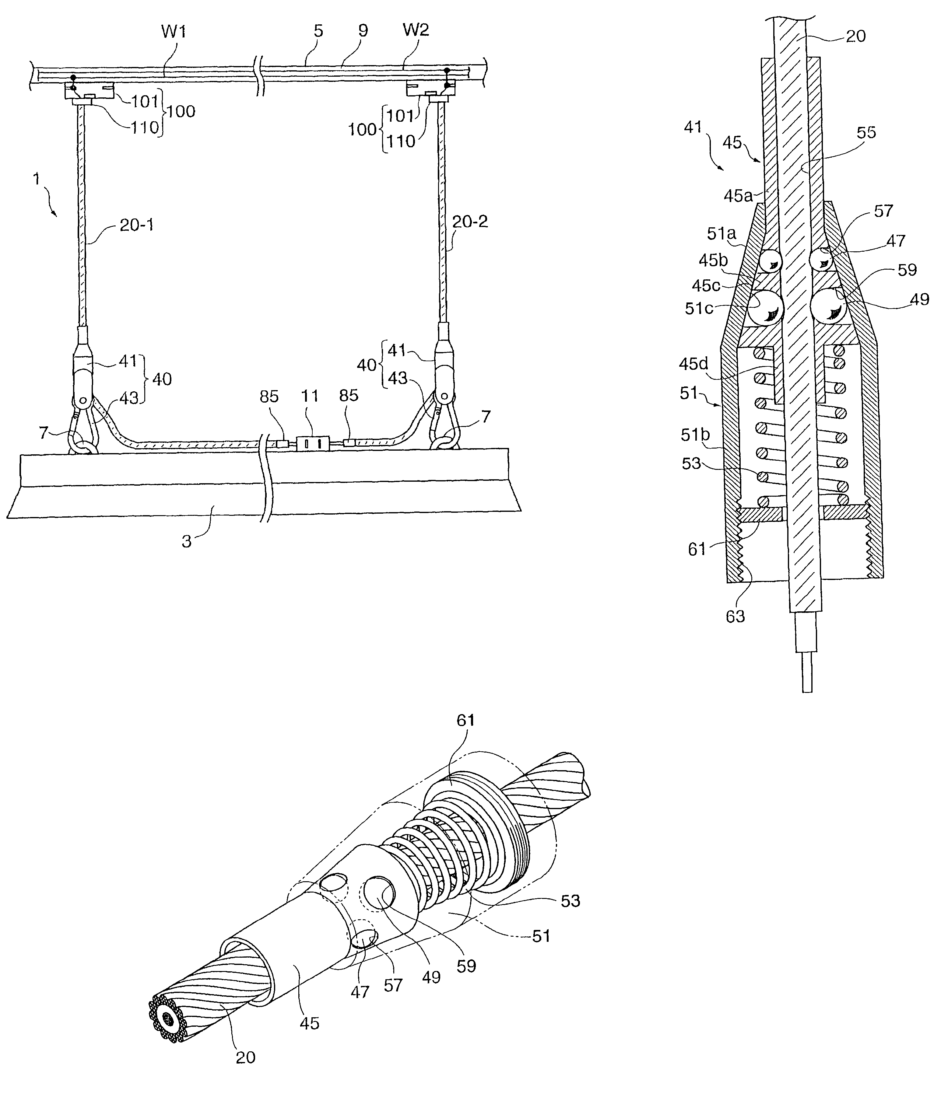
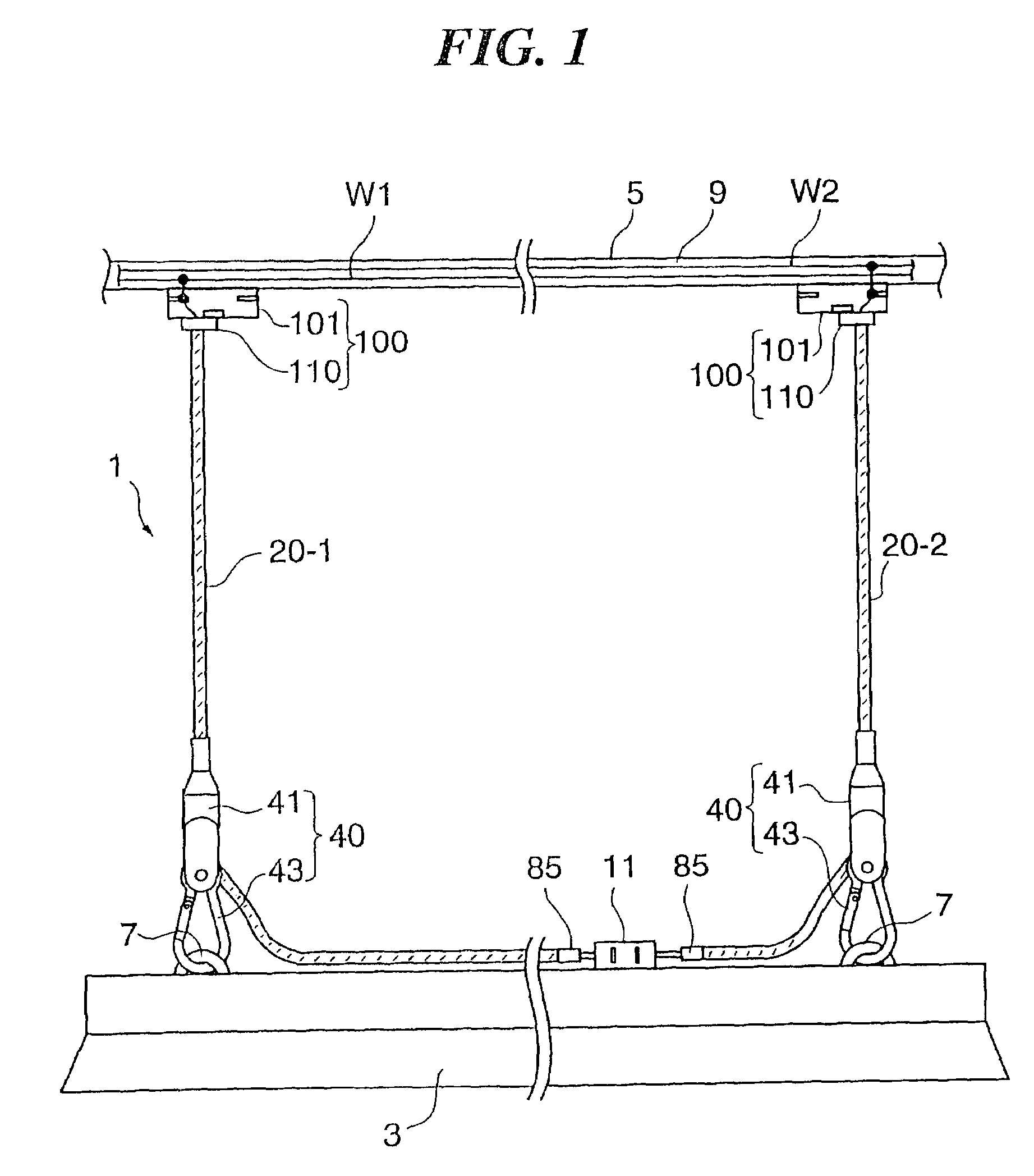
[0139]The electrical apparatus suspension unit 201 of the embodiment also suspends a lighting apparatus from the ceiling 5 by using the two power supply wires 20-1 and 20-2. In the embodiment, a grounded conductor cable W1 and a voltage-applied conductor cable W2 are led out from an F-cable C and are connected to each of wiring terminals 13 mounted on the ceiling 5. The electrical apparatus suspension unit 201 has substantially the same structure as the device 1 as shown in FIG. 1 except that an upper holder 210 has a structure for the structure of the wiring terminal 13.

[0140]The upper holder 210 is composed of a plug 211 for the wiring terminal 13 and the electrode support 110 (as shown in FIG. 10) having the same structure as that of the device 1 shown in FIG. 1. The electrode support 110 is mounted to the plug 211. The plug 211 is mounted to the wiring terminal 13. The core...

third embodiment

[0141]FIG. 12 is a drawing showing an electrical apparatus suspension unit according to the present invention.

[0142]The electrical apparatus suspension unit 301 of the embodiment suspends the lighting apparatus 3 from the ceiling 5 by using the two power supply wires 20-1 and 20-2. In this embodiment, the rail 5 is not laid on the ceiling 5, and the lighting apparatus 3 has a terminal (a pressure joint terminal) 17 inside thereof.

[0143]Since a rail or a wiring terminal is not laid on the ceiling 5, it is necessary to connect the upper ends of the wires 20 to a wiring terminal 15 above the ceiling. A grounded conductor cable W1 and a voltage-applied conductor cable W2 led from a F-cable C are connected to the wiring terminal 15 above the ceiling. The wires 20 are maintained to the ceiling 5 by the upper holder 310 at the upper portions thereof.

[0144]FIG. 13 is a drawing showing a structure of the upper holder.

[0145]The upper holder (a wire grip with a holding part) 310 is composed of...

fifth embodiment

[0173]FIG. 17 is a drawing showing a structure of an electrical apparatus suspension unit according to the present invention.

[0174]The electrical apparatus suspension unit 501 suspends a lighting apparatus 3 from the ceiling by one power supply wire, similar to the unit of the FIG. 15. In this embodiment, however, the lighting apparatus 3 operates at low-volt (36V or lower, AC or DC) and has a working power of 12V60 W or lower than the apparatus of FIG. 15. And, in this embodiment, since a wiring terminal is not mounted on the ceiling, it is necessary to connect the upper end of the wire to a wiring terminal above the ceiling.

[0175]FIG. 18 is a cross-sectional drawing showing the power supply wire of the lighting apparatus suspension unit.

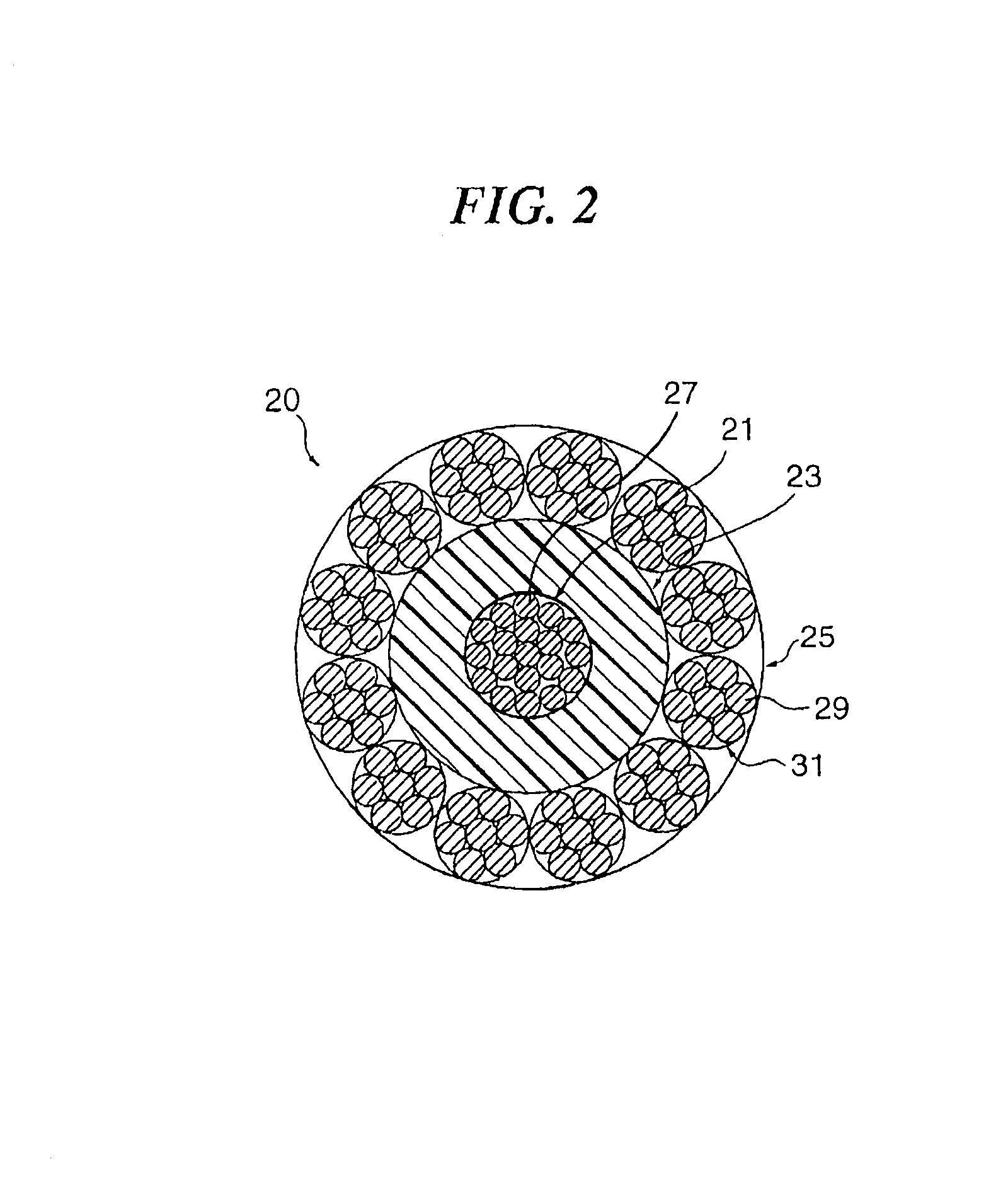
[0176]The power supply wire 520 comprises a core wire 521, an insulating layer 523 covering the core wire 521 and an outer layer 525 covering the insulating layer 523. In other words, the power supply wire 520 has a structure in which the outermost...


PUM

PropertyMeasurementUnit
diameteraaaaaaaaaa
tensile strengthaaaaaaaaaa

Abstract

The electrical apparatus suspension unit 1 is provided with two power supply wires 20-1 and 20-2 by which the electrical apparatus 3 is conducted and suspended from the ceiling 5. Each of the wires 20 is connected to the hung member of the electrical apparatus 3 at the lower end by the a lower holder 40, and connected to the rail 9 laid on the ceiling 5 at the upper end by an upper holder 100. The power supply wire 20 comprises a core wire 21, an insulating layer 23 covering the core wire 21 and an outer layer 25 covering the insulating layer 23. The core wire 21 of the power supply wire 20-1 conducts to a grounded conductor cable W1 and the core wire 21 of another power supply wire 20-2 conducts to a voltage applied conductor cable W2. The power supply wires 20 having high tensile strength enables to suspend the electrical apparatus and also supply power thereto.

Description

[0001]This application is a U.S. National Phase Application under 35 USC 371 of International Application PCT / JP2003 / 013374 filed Oct. 20, 2003.FIELD OF THE INVENTION[0002]The present invention relates to a power supply wire capable of serving as suspending an electrical apparatus as well as power-supplying thereto. Furthermore, the present invention relates to an electrical apparatus suspension unit comprising the power supply wire, a wire grip for connecting the wire and the like.BACKGROUND OF THE INVENTION[0003]In order to suspend a lighting apparatus from a ceiling, a single suspension cord unitizing a suspension string (a reinforced member) and a power supply cable is employed. In such a case, since the suspension cord serves as power supplying to the lighting apparatus as well as supporting the weight thereof, it is easily installed. And, such the suspension cord has a simple good appearance.[0004]An exemplary suspending cord for an electrical apparatus is disclosed in Japanes...

Claims


Application Information

Patent Timeline
Patent Type & Authority Patents(United States)
IPC IPC(8): H01B11/06F16G11/04F16G11/10F21V21/104F21V21/112F21V21/16H02G3/20
CPCF16G11/04F16G11/10F16M13/02F21S8/06F21S8/068F21V21/104F21V21/112F21V21/16H02G3/20F16M13/027F16M11/046F16G11/108
Inventor ARAKAWA, HIDEO
Owner A G K
Why Eureka
Try Eureka