Feed forward amplifier for multiple frequency bands

a technology of feed forward amplifier and frequency band, which is applied in the direction of amplifiers, electrical devices, and amplifier modifications to reduce noise influence, can solve the problems of single hardware actually handling a plurality of radio systems that has not yet been implemented, and it is difficult to maintain an excellent balance, so as to achieve adaptive distortion, reduce power consumption, and simplify the configuration of feed forward amplifier collectively amplifying a plurality of frequency bands

Inactive Publication Date: 2008-02-26
NTT DOCOMO INC
View PDF18 Cites 34 Cited by
  • Summary
  • Abstract
  • Description
  • Claims
  • Application Information

AI Technical Summary

Benefits of technology

[0021]According to the present invention, it is possible to implement a feed forward amplifier making possible adaptive distortion compensation, even with respect to changes among a plurality of frequency bands. The configuration of a feed forward amplifier collectively amplifying a plurality of frequency bands is simplified, so a reduction in power consumption can be implemented. According to the configuration of the present invention, it is possible to make an adjustment to a specific distortion compensation level for each frequency band, independently of the electric length difference of the delay lines constituting a linear signal path. By the fact that it is possible to change the center frequency or the bandwidth of the frequency band extractor, an adjustment can be made to a specific compensation level for each frequency band.
[0022]In this way, the feed forward amplifier of the present invention is capable of linearly amplifying a frequency band corresponding to the service situation of the radio system. Consequently, the present invention can make unnecessary additional equipment that would accompany a change in the frequency band and an increase in carrier waves.
[0023]Also, the present invention uses variable filters in the feed forward amplifier in order to make changes in the frequency band simple and inexpensive. Also, the pass band of the variable filter is controlled so as to match the used band. Consequently, even with one feed forward amplifier, it is possible to handle the frequency changes of the radio system. Also, since the feed forward amplifier of the present invention can also switch the operating band due to an instruction from an operations center to switch the frequency bands, the need to spend an enormous amount of labor on radio system adjustments disappears. In addition, since the feed forward amplifier of the present invention can detect the frequency band of the received signal and automatically switch the frequency band, it is also possible to change the frequency band dynamically, even if the transmitter side changes the frequency band. Also, rather than configuring a feed forward amplifier for each frequency band, the case of making an implementation with a single feed forward amplifier is more advantageous from the viewpoints of device scale and power consumption.

Problems solved by technology

In practice, it is not simple to completely maintain a balance of the distortion detection circuit and the distortion elimination circuit.
Also, even if tentatively the initial settings are perfect, since the properties of the amplifier change due to fluctuations in ambient temperature, power supply, and the like, it is extremely difficult to preserve an excellent balance which is stable over time.
However, a single hardware actually handling a plurality of radio systems is something that has not reached implementation.
However, in the vector adjusters developed this far, it has not been possible to track a signal rotating at a velocity like that.
Also, as for the vector adjusters discussed this far, it has not been possible to simultaneously set an optimal amplitude and phase, with respect to plural input signals, for structural reasons.
However, it is not possible to carry out optimal vector adjustment which tracks a frequency difference of 700 MHz.
Consequently, the conventional feed forward amplifier has not been able to simultaneously amplify the 800 MHz band signal and the 1.5 GHz band signal at or below a prescribed distortion compensation level.
Consequently, in the conventional feed forward amplifier, the adjustment of distortion compensation could not be made to correspond with the frequency band changes.
Also, it was not possible for the conventional dual-band feed forward amplifier in which the distortion compensated frequency band was fixed to adaptively change the operating frequency.
Consequently, an enormous amount of labor and time is required to readjust a large number of feed forward amplifiers.
A feed forward amplifier configuration making this kind of labor and time expense unnecessary was required.
This was so because loop adjustment by the frequency difference of f1 and f3 was not possible, as mentioned above, due to the fact that the operating frequencies of a conventional dual-band feed forward amplifier are fixed.
However, having fixed filters and vector adjusters able to handle all the frequency bands amounts to having fixed filters and vector adjusters which are not used something which runs counter to configuring a cost-effective feed forward amplifier.

Method used


Image

  • Feed forward amplifier for multiple frequency bands
  • Feed forward amplifier for multiple frequency bands
  • Feed forward amplifier for multiple frequency bands

Examples


first embodiment

1. FIRST EMBODIMENT

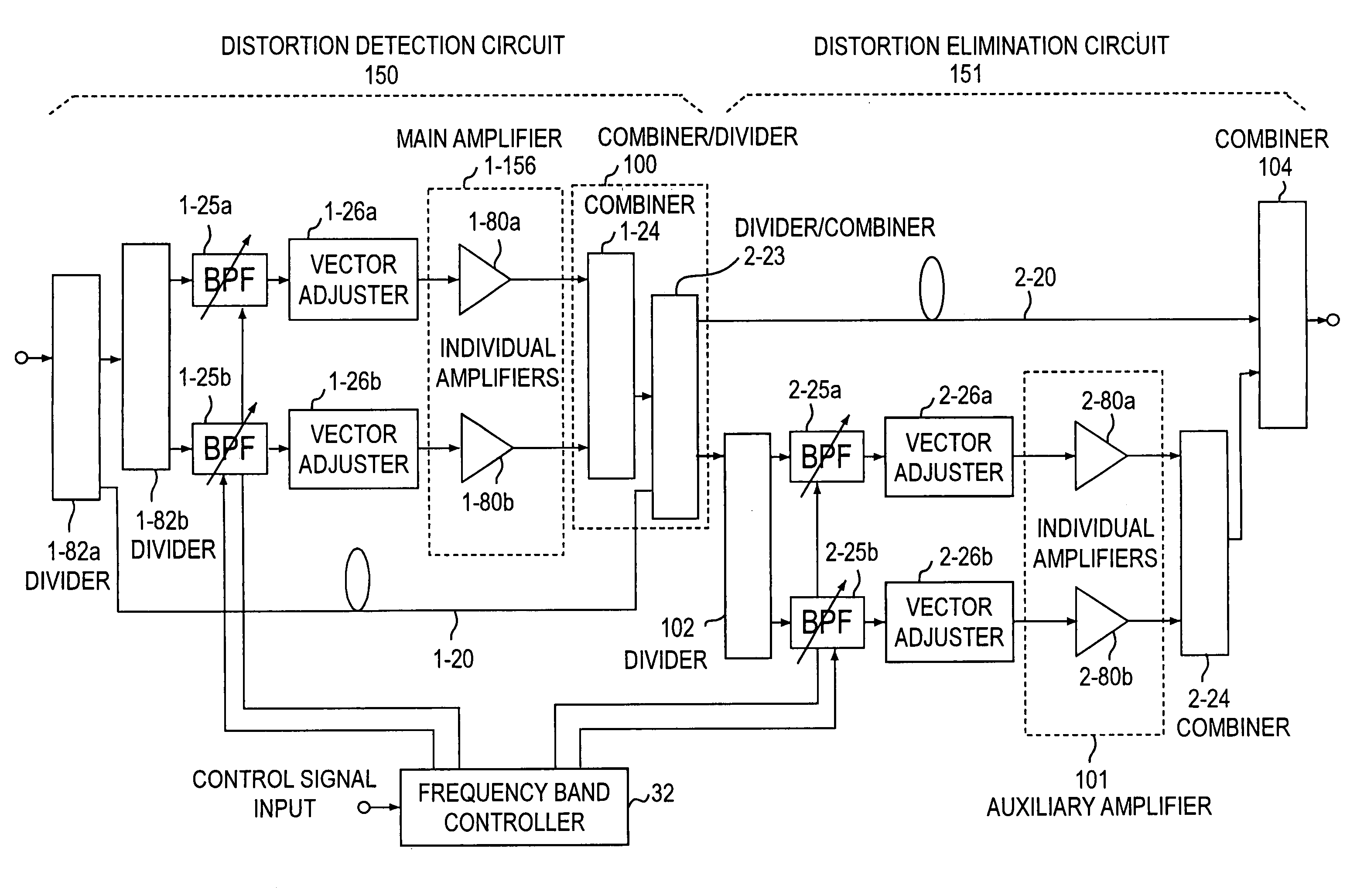
[0065]In FIG. 11, Embodiment 1 of a feed forward amplifier according to the present invention is shown. In order to simplify the drawings and explanations for all the embodiments below, the explanation will be given taking the number of used frequency bands to be 2, but in general, two or more frequency bands may be used.

[0066]In the explanation below, “1-” is attached in front of reference numerals of the multiple frequency band signal processing circuit forming the distortion detection circuit and “2-” is attached in front of reference numerals of the multiple frequency band signal processing circuit forming the distortion elimination circuit. However, in the case of intrinsic numerals, the notation is not used.

[0067]A combiner 1-24 of the multiple frequency band signal processing circuit constituting distortion detection circuit 150 functions as a combiner / divider 100, together with a divider 2-23 of the multiple frequency band signal processing circuit constit...

second embodiment

2. SECOND EMBODIMENT

[0075]In FIG. 12, Embodiment 2 is shown. Embodiment 2 is an embodiment in which the multiple frequency band signal processing circuit shown in FIG. 10 has been applied as distortion elimination circuit 151. In the Embodiment 2 feed forward amplifier as well, vector adjustment is performed using vector adjusters 1-26a, 1-26b, 2-26a, and 2-26b for each frequency band. If sufficient isolation is provided between the vector adjustment paths, there is no influence exerted on the vector adjusters of the other frequency bands, even if the vector adjuster of one frequency band is adjusted. Consequently, it is possible to carry out distortion compensation independently for each frequency band. Also, if vector adjustment paths are added, it is possible to flexibly add frequency bands which are distortion compensated.

[0076]An auxiliary amplifier 2-156 of the distortion elimination circuit has one common amplifier 2-91 which simultaneously amplifies a plurality of frequency ...

third embodiment

3. THIRD EMBODIMENT

[0077]In FIG. 13, Embodiment 3 is shown. Embodiment 3 is an example using the multiple frequency band signal processing circuit shown in FIG. 10 as distortion detection circuit 150. The feed forward amplifier of Embodiment 3 also carries out vector adjustment by using, for each frequency band, vector adjusters 1-26a, 1-26b, 2-26a, and 2-26b. If sufficient isolation is provided between the vector adjustment paths, there is no influence exerted on the other vector adjusters, even if the vector adjuster of one frequency band is adjusted. Consequently, it is possible to perform distortion compensation independently for each frequency band. Also, if vector adjustment paths are added, it is possible to flexibly add frequency bands which are distortion compensated.

[0078]Main amplifier 1-156 of distortion detection circuit has one common amplifier 1-91 which simultaneously amplifies a plurality of frequency bands, as shown in FIG. 10. Consequently, there can be expected a...


PUM


Abstract

The present invention has for its object to provide, in an environment where plural radio systems coexist, a feed forward amplifier for multiple frequency bands, capable of adaptively selecting the frequency band which is used.The feed forward amplifier of the present invention comprises a distortion detection circuit and a distortion elimination circuit and has first and second variable frequency band extractors 25a and 25b provided in series with respective vector adjustment paths 21a and 21b. Also, the feed forward amplifier comprises a frequency band controller which varies the frequency band of variable frequency band extractors 25a and 25b and has been designed, by changing the frequency band of first and second variable frequency band extractors 25a and 25b in response to a frequency switching request from the outside, to be able to adaptively control the frequency band in which distortion is compensated.

Description

BACKGROUND OF THE INVENTION[0001]1. Field of the Invention[0002]The present invention pertains to a power amplifier for mobile communications which adaptively changes the frequency band among a plurality of frequency bands. In particular, it pertains to a feed forward amplifier for multiple frequency bands which collectively amplifies a plurality of frequency bands.[0003]2. Description of Related Art[0004]The base configuration of a conventionally used feed forward amplifier is shown in FIG. 1. The feed forward amplifier includes two signal processing circuits. One is a distortion detection circuit 150 and the other is a distortion elimination circuit 151. Distortion detection circuit 150 is composed of a main amplifier signal path 153 and a linear signal path 154. Distortion elimination circuit 151 is composed of a main signal path 158 and a distortion injection path 159. Main amplifier signal path 153 (also called a vector adjustment path) is composed of a vector adjuster 155 and ...

Claims


Application Information

Patent Timeline
Patent Type & Authority Patents(United States)
IPC IPC(8): H03F1/00
CPCH03F1/3229H03F1/32
Inventor SUZUKI, YASUNORINARAHASHI, SHOICHI
Owner NTT DOCOMO INC
Why Eureka
Try Eureka