LED lighting system for line scan camera based multiple data matrix scanners

a technology of multiple data matrix and led lighting, which is applied in the direction of signalling system, identification means, instruments, etc., can solve the problems of difficult repositioning of surface mount leds, color and contrast in texture cannot be detected simultaneously, and scanners using conventional lighting cannot clearly distinguish the difference between manufacturing texture and two-dimensional data matrix code textur

Inactive Publication Date: 2008-02-26
DELTA DESIGN
View PDF6 Cites 55 Cited by
  • Summary
  • Abstract
  • Description
  • Claims
  • Application Information

AI Technical Summary

Benefits of technology

[0005]According to one embodiment of the invention, a LED lighting system for reading multiple data matrix codes on a device populated transport media with a line scan camera, comprises a light housing, a plurality of LED circuit bars, having a plurality of LEDs, mounted to an inner surface of the light housing arranged to provide high angle lighting and low angle lighting, wherein at least one of the plurality of LED arrays has a plurality of LEDs mounted on a mounting surface of the LED circuit bar that faces the transport media at an angle of sixty degree or less relative to the mounting surface of the LED array, and a light controller operatively connected to the light housing to selectively control the light intensity, the light distribution and the angle of the LEDs on each of the plurality of LED array bars, whereby the LED lighting system can reduce texture noise and detect contrast in color or contrast in texture on a device populated transport media.

Problems solved by technology

However, scanners using conventional lighting do not clearly discern the difference of manufacturing texture from two dimensional data matrix code texture.
Moreover, due to the characteristics of the single light bar contrast in color and contrast in texture can not be detected simultaneously.
However, surface mount LEDs are difficult to reposition.

Method used


Image

  • LED lighting system for line scan camera based multiple data matrix scanners
  • LED lighting system for line scan camera based multiple data matrix scanners
  • LED lighting system for line scan camera based multiple data matrix scanners

Examples


Embodiment Construction

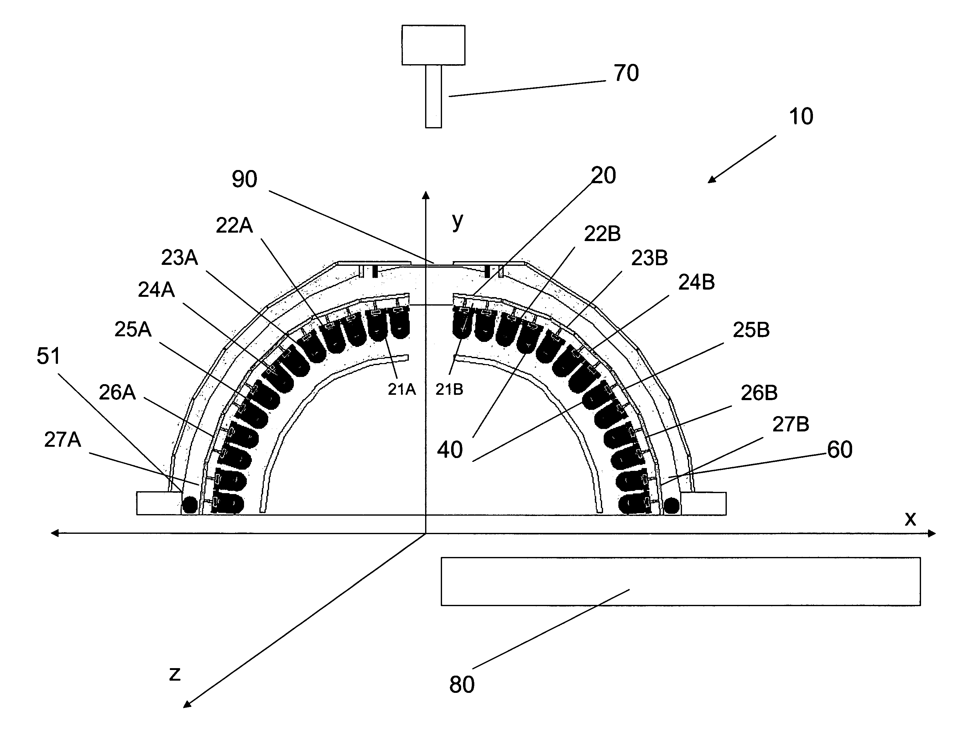
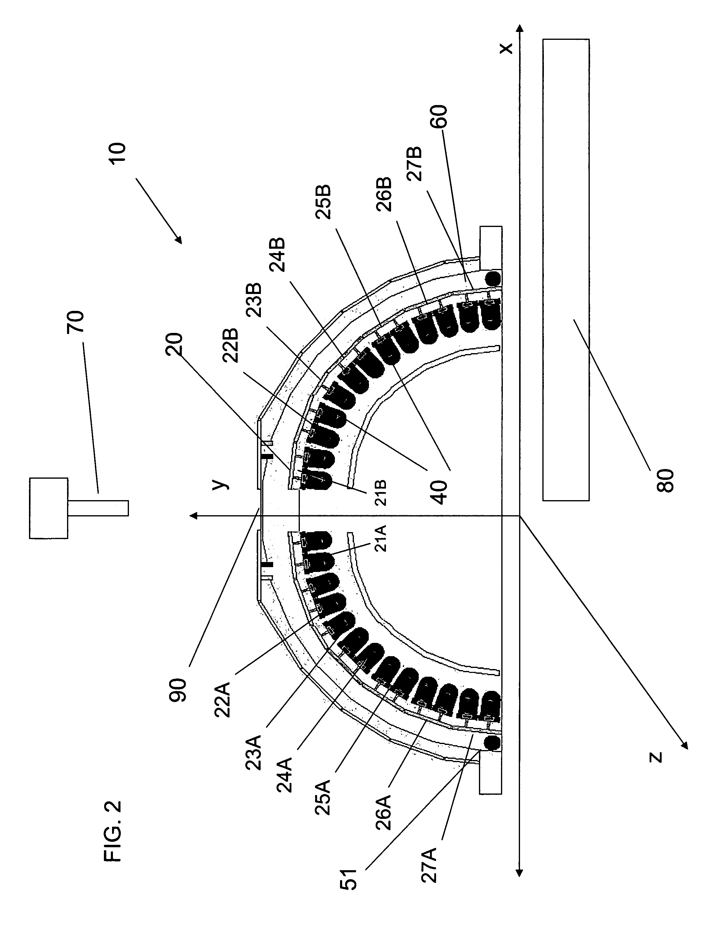
[0016]An exemplary LED lighting system according to the present invention is now described in reference to the accompanying drawings. It will be appreciated that the lighting system according to the invention may be used advantageously with a backend IC automated handling machine (for example, as shown in FIG. 9) that sorts devices into categories based on a unique identification code on each device. In turn, each code is associated with a category number. The automated handling equipment uses a vision system or scanner to identify each device. The system keeps track of the device location inside each tray and sorts them into trays, particularly JEDEC trays, such that devices of the same category are in the same tray. Of course, other applications may be apparent to those skilled in the art.

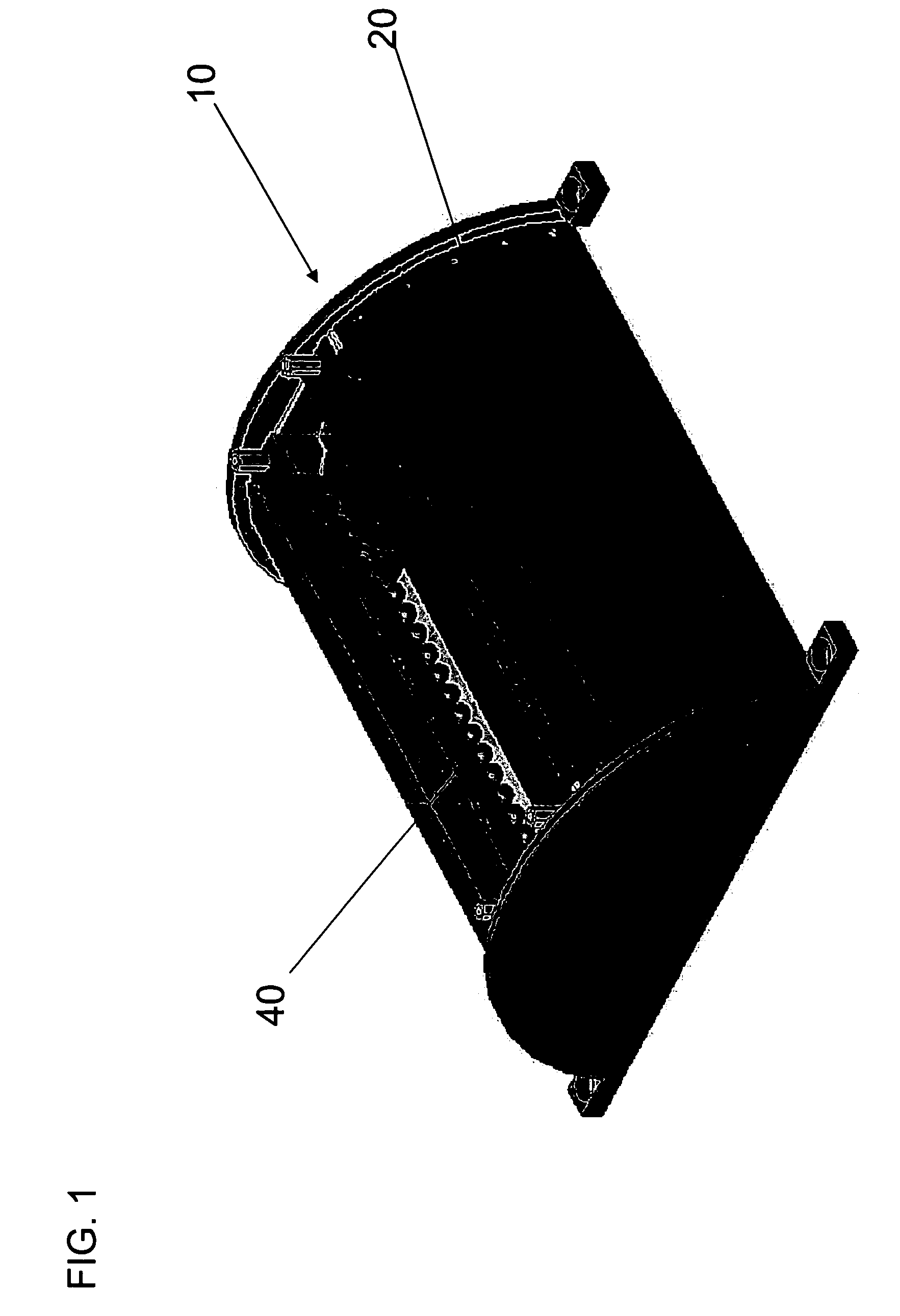
[0017]As shown in FIGS. 1, 4 and 5 the LED lighting system 1 has a LED light housing 10 formed in a half-cylindrical shape. The inner surface of the LED light housing 10 is populated with a plura...


PUM


Abstract

A LED lighting system for reading multiple data matrix codes on device populated transport media with a line scan camera, includes a light housing, a plurality of LED circuit bars, having a plurality of LEDs, mounted to an inner surface of the light housing arranged to provide high angle lighting and low angle lighting and a light controller operatively connected to the light housing to selectively control the light intensity, the light distribution and the angle of the LEDs on each of the plurality of LED array bars, whereby the LED lighting system can reduce texture noise and detect contrast in color or contrast in texture on the device populated transport media. The LED lighting system includes a device cooling system having an air compressor for cooling the LEDs such that they can operate at an optimal level.

Description

CROSS-REFERENCE TO RELATED PATENT APPLICATIONS[0001]This instant application claims priority to and benefit of U.S. Provisional Application 60 / 666,307 filed Mar. 30, 2005 the disclosure of which is incorporated by reference herein in its entirety.FIELD OF INVENTION[0002]The present invention relates generally to an LED lighting system, and more particularly to an LED lighting system for a line scan camera based multiple data matrix scanner.BACKGROUND OF THE INVENTION[0003]Semiconductor devices are commonly sorted into different categories based on performance characteristics determined during test by specialized processing equipment. Transport media include any fixture or carrier designed for transporting semiconductor devices internal or external to the processing equipment. An example is a plastic tray as specified by the JEDEC Design Standard. In most cases, the processing equipment has a vision system and a lighting system to aid in identifying and sorting the devices.[0004]Gene...

Claims


Application Information

Patent Timeline
Patent Type & Authority Patents(United States)
IPC IPC(8): G08B5/22
CPCG06K7/10722G06K7/10732
Inventor DING, KEXIANG KENAVERY, BRIANUEKERT, KENNETH B.KABBANI, SAMERSETHANANT, TORSAK
Owner DELTA DESIGN
Why Eureka
Try Eureka