Optical attenuator

a technology of optical attenuator and polarising element, which is applied in the field of optical attenuator, can solve the problems of too small dynamic range, too large dependence of dynamic range, and the amount of optical attenuation that can be changed

Inactive Publication Date: 2008-02-26
KOHOKU KOGYO CO LTD
View PDF13 Cites 4 Cited by
  • Summary
  • Abstract
  • Description
  • Claims
  • Application Information

AI Technical Summary

Problems solved by technology

However, optical attenuators of the conventional configuration have a problem that the range, in which the amount of optical attenuation can be changed, in other words, the dynamic range is too small.
Also, another problem is found that the temperature-dependence of the dynamic range is so large that the lower temperature drops, the smaller the dynamic range becomes.

Method used


Image

  • Optical attenuator
  • Optical attenuator
  • Optical attenuator

Examples


embodiments

Embodiment 1

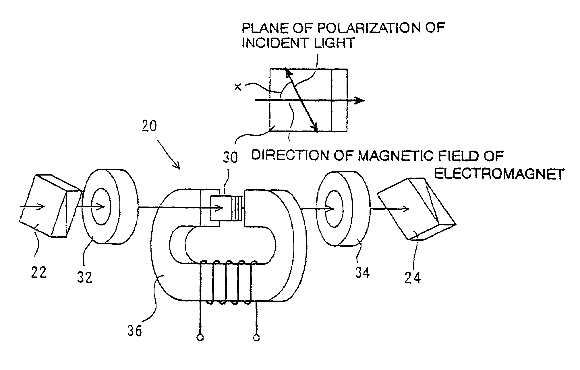
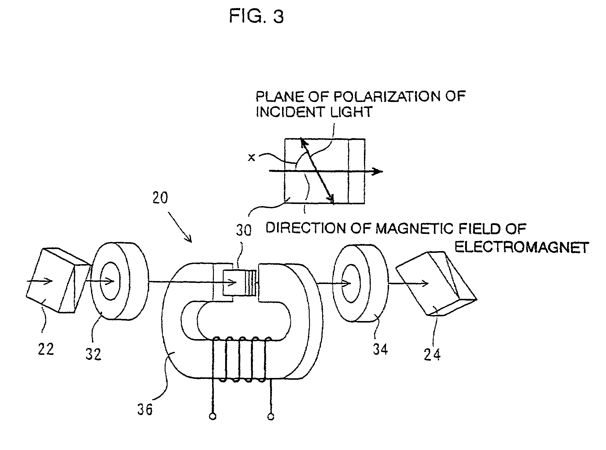
[0039]A system shown in FIG. 3 was manufactured, and the relation among the extinction ratio of the garnet single crystal and the angle x (an angle formed between the plane of polarization of light passed through the polarizer, in other words, the plane of polarization at the entry position of the garnet single crystal and the magnetic field direction of the electromagnet) and angle z (the rotational angle of the plane of polarization when light passes through the garnet single crystal) were studied. The angle z was allowed to vary by changing of the magnetic field to be applied by the electromagnet, and the angle x was allowed to vary by turning of the polarizer (compound polarizing prism). For information, the magnetic field intensity of the permanent magnet is 16.6 kA / m.

[0040]First, the garnet single crystal was manufactured as follows: With PbO—B2O3—Bi2O3 as a solvent, by the LPE method, on the face (111) of a non-magnetic garnet substrate 40, with grating constant b...

embodiment 2

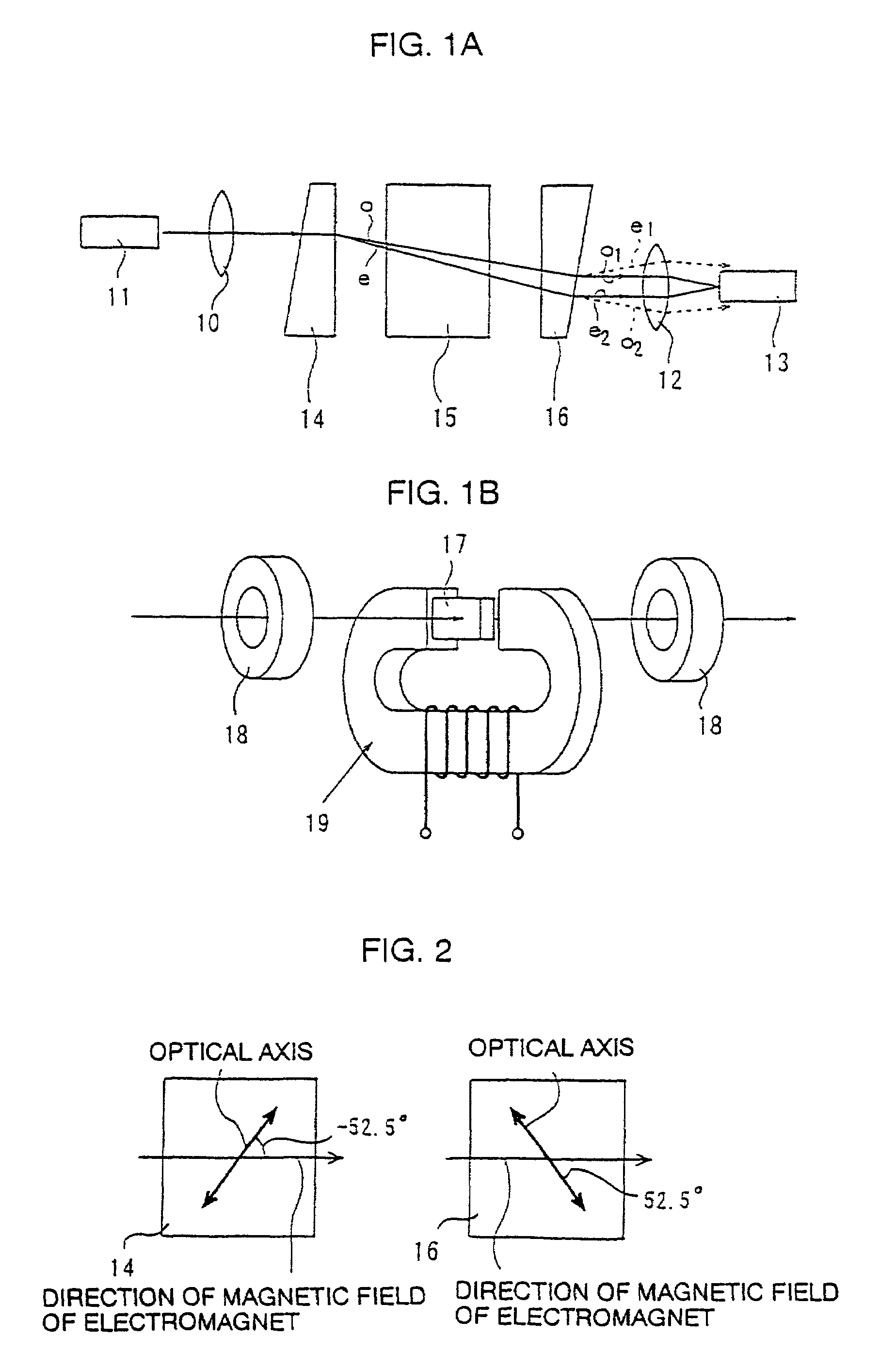
[0048]The present invention can be applied to a polarization non-dependent optical attenuator as shown in FIG. 1. A measurement system was manufactured, with a wedge type birefringent crystal (here, a rutile crystal) used for the polarizer and the analyzer in the measurement system shown in FIG. 3. External magnetic field to be applied to the garnet single crystal comprises two directions, a fixed magnetic field (16.6 kA / m) by the permanent magnet in a parallel direction to the light beam direction, and a variable magnetic field by the electromagnet in a direction intersecting at right angles. FIG. 12 shows the polarizer and analyzer, viewed from the traveling direction of light. A wedge-type birefringent crystal which functions as a polarizer 14 is set, so that an angle x formed between the applying magnetic field direction by the electromagnet to be applied in a direction intersecting the optical axis at right angles and the optical axis becomes −7.5 degrees. When viewed from the ...


PUM


Abstract

An optical attenuator with increased dynamic range and reduced temperature-dependence over the dynamic range. The optical attenuator has a Faraday rotational angle variable device which applies an external magnetic field to light polarized by a garnet crystal, and a polarizer and an analyzer disposed at the front and rear of the optical axis of the device. There is an angle x formed between the plane of polarization of the light incident to the garnet crystal and the magnetic field orthogonal to the optical axis, where an angle y is formed between the polarizer and the analyzer, and the angle x is set to satisfy {(−z / 2)+90×n}−12<x<{(−z / 2)+90×n}+12 (n=0, 1, 2 or 3), where z=y±90; z is the angle of rotation of the plane of polarization caused by the Faraday rotational angle variable device.

Description

TECHNICAL FIELD[0001]The present invention relates generally to an optical attenuator having a polarizer and an analyzer integrated therein at the front and rear of the optical axis of a Faraday rotational angle variable device, and more particularly, to an optical attenuator that is able to widen its dynamic range and also able to reduce its temperature-dependence, by allowing an angle to lie within a specific range, the angle being formed between the direction of a component, orthogonal to the direction of light, of a magnetic field applied to a magnetic garnet single crystal in the Faraday rotational angle variable device, and the plane of polarization of the incident light to a garnet single crystal.BACKGROUND ART[0002]An optical communication system needs an optical attenuator to control the amount of light passing therethrough. The optical attenuator is configured to provide a polarizer and an analyzer at the front and rear (the incoming side and the outgoing side) of the opti...

Claims


Application Information

Patent Timeline
Patent Type & Authority Patents(United States)
IPC IPC(8): G02B5/30
CPCG02B27/281G02F1/093G02F2203/48
Inventor KAWAI, HIROTAKAUMEZAWA, HIROMITSUKOJIMA, ISAONAKATA, HIDENORISAHASHI, TERUHISA
Owner KOHOKU KOGYO CO LTD
Why Eureka
Try Eureka