Sonic logging tool including receiver and spacer structure

a technology of a receiver and a spacer, which is applied in the field of sonic logging tools including receivers and spacers, can solve the problems of flexural signal propagation, inability to use tools in any borehole, and high undesirable effects, and achieve the effect of removing or preventing the arrival of flexural tools

Inactive Publication Date: 2008-02-26
SCHLUMBERGER TECH CORP
View PDF20 Cites 23 Cited by
  • Summary
  • Abstract
  • Description
  • Claims
  • Application Information

AI Technical Summary

Benefits of technology

[0008]To date, no approach has been completely successful in removing or preventing flexural tool arrivals. It is an object of the present invention to provide a tool structure in which the problem of flexural tool arrival can be handled in a way which does not compromise the ability of the tool to make dipole measurements of the formation.

Problems solved by technology

One frequently observed problem in dipole logging is the propagation of a flexural signal from the source to the receivers along the tool itself.
This signal, often known as a “tool arrival”, interferes with the detection of the corresponding signal that has propagated in the formation and so is highly undesirable.
Such an approach is effective in preventing the tool arrival from passing directly along the tool body from the source to the receiver but has the problem in that the tool cannot be used in any borehole which is not vertical, or nearly so.
Since boreholes that are deviated from vertical are very common, such a tool has limited application.
This structure also does not address the problem of a flexural signal coupling into the receiver structure from the borehole and then propagating along the receiver.
However, since this is not a rigid structure, it may be necessary to also provide a housing or sleeve to make the tool able to operate in deviated boreholes.
To date, no approach has been completely successful in removing or preventing flexural tool arrivals.

Method used


Image

  • Sonic logging tool including receiver and spacer structure
  • Sonic logging tool including receiver and spacer structure
  • Sonic logging tool including receiver and spacer structure

Examples


Embodiment Construction

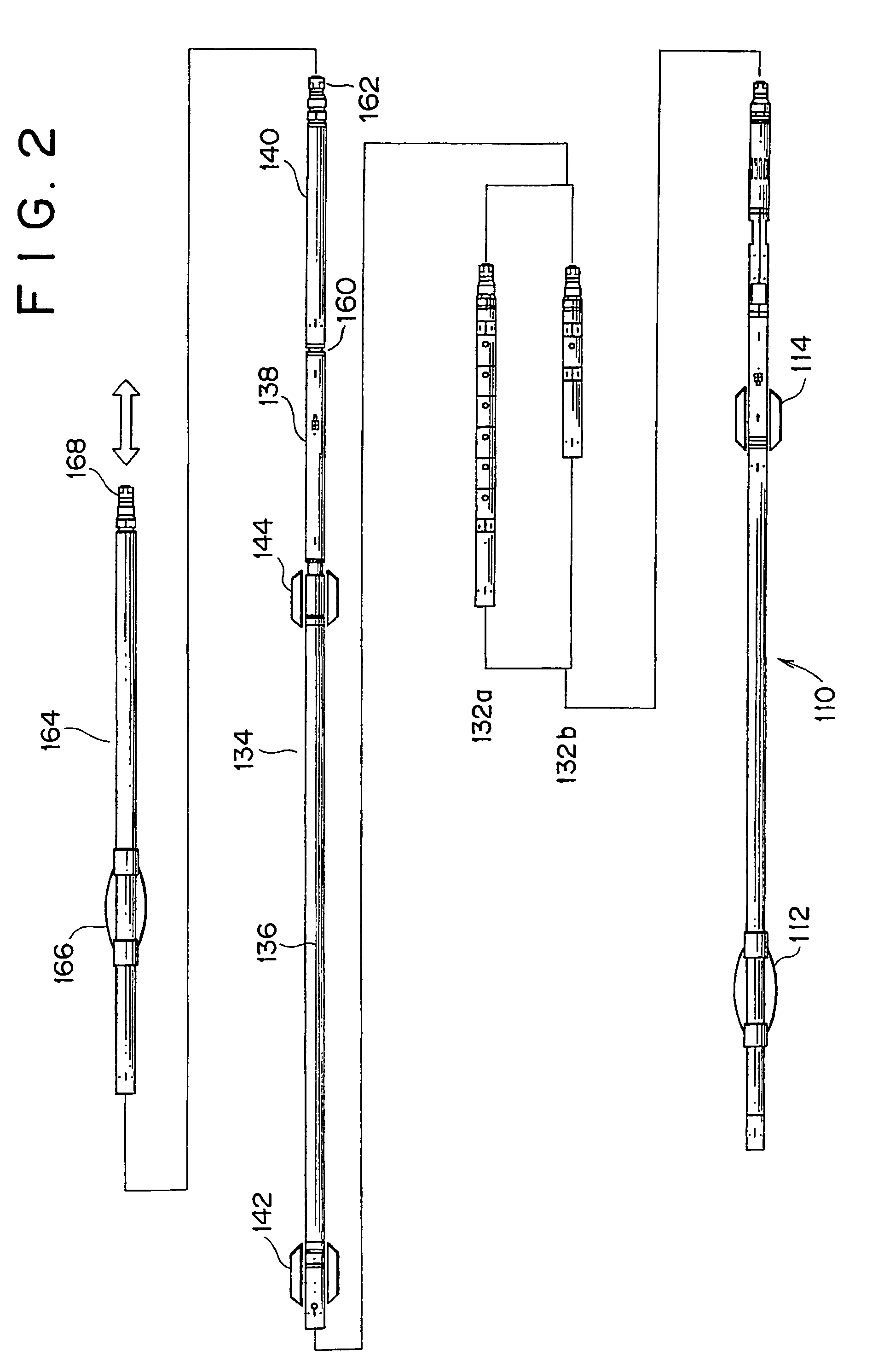
[0032]Referring now to FIG. 2, there is shown therein a borehole logging tool including a receiver section and a spacer section according to embodiments of the invention. The tool shown in FIG. 2 comprises an acoustic transmitter module 110 including a centraliser 112 and a standoff 114. The transmitter module 110 is shown in more detail in FIG. 3 and comprises an electronics section 120 with appropriate electronics and drive circuitry for the acoustic sources, an oil volume compensator section 122, a first dipole source 124 (nominal “Y” direction), a second dipole source 126 (orthogonal to the first source 124, nominal “X” direction) and a monopole source 128. The dipole sources 124, 126 are substantially as described in the applicants' copending U.S. patent application Ser. No. 09 / 537,836 entitled “Dipole Logging Tool”, filed Mar. 2, 2000 (incorporated herein by reference) and the monopole source 128 is substantially as described in U.S. Pat. No. 5,036,945 (incorporated herein by ...


PUM


Abstract

A formation logging tool having a substantially continuous central mandrel with regularly spaced mass blocks disposed thereon, at least some of the mass blocks carrying sensors such as receivers. By adopting this structure, the tool can be made to behave as a mass-spring structure and its flexural and extensional behaviour controlled such that its dispersion curve does not extend into the dispersion curve of the formation to be logged. The structure can be applied to the whole of the logging tool or just to the receiver section and/or any spacer section between the receiver and the transmitter section.

Description

FIELD OF THE INVENTION[0001]The present invention relates to structures for use in receiver arrays and spacers for use in sonic borehole logging tools. In particular, the invention relates to a structure having a particular flexural behavior which is designed to reduce the impact of interference with sonic logging measurements.BACKGROUND OF THE INVENTION[0002]The field of sonic logging of boreholes in the oil and gas industry involves making acoustic measurements in the borehole at frequencies typically in the range 500 Hz-20 kHz. Below this range is typically considered as the seismic domain, above it the ultrasonic domain. A summary of the general techniques involved in borehole acoustic logging can be found in GEOPHYSICAL PROSPECTING USING SONICS AND ULTRASONICS, Wiley Encyclopedia of Electrical and Electronic Engineering 1999, pp 340-365.[0003]One example of a sonic logging tool used by Schlumberger is the Dipole Sonic Imaging tool (DSI), shown in schematic form in FIG. 1. The D...

Claims


Application Information

Patent Timeline
Patent Type & Authority Patents(United States)
IPC IPC(8): G01V1/52
CPCG01V1/523Y10S367/911
Inventor HOYLE, DAVIDTASHIRO, HITOSHIOTSUKA, AKIRAPABON, JAHIRSUGIYAMA, HITOSHI
Owner SCHLUMBERGER TECH CORP
Why Eureka
Try Eureka