Instantaneous fuel-fired water heater with low temperature plastic vent structure

a fuel-fired water heater and low-temperature technology, which is applied in the direction of heating types, domestic hot-water supply systems, lighting and heating apparatuses, etc., can solve the problems of high cost, difficult installation, and inability to meet the needs of users, and achieve the effect of reducing the exterior surface temperature and low cos

Active Publication Date: 2008-03-04
RHEEM MFG CO
View PDF21 Cites 11 Cited by
  • Summary
  • Abstract
  • Description
  • Claims
  • Application Information

AI Technical Summary

Benefits of technology

[0007]The use of blower-discharged air as combustion air delivered to the burner, and heat exchanger-bypassing cooling air to reduce the temperature of combustion gas discharged from the fluid heating apparatus permits the temperature of the cooled combustion gas to be less than about 200° F. so that a low cost plastic vent system can be connected to the outer housing, at the combustion gas outlet opening therein, to receive and discharge the cooled combustion gas.
[0008]According to other aspects of the invention, the first flow path is enveloped by the second flow path, with the first flow path being defined by a pipe-based heat exchanger disposed within a combustion chamber through which the second flow path extends. Preferably, the third flow path is interposed between and at least partially bounded by an interior surface portion of the outer housing and an exterior surface portion of the heat exchange structure. Preferably a fourth flow path is also disposed within the outer housing, between the heat exchanger structure and a portion of the outer housing, for flowing ambient air through the outer housing to an inlet portion of the blower apparatus. Air flow through the third and fourth flow paths serves to reduce the exterior surface temperature of the outer housing.

Problems solved by technology

These necessary stainless steel vent systems, which are usually specified and / or supplied in kit form with the water heater, are expensive, difficult to install, non-interchangeable across various manufacturers, and difficult to source through retail and wholesale distribution centers.

Method used


Image

  • Instantaneous fuel-fired water heater with low temperature plastic vent structure
  • Instantaneous fuel-fired water heater with low temperature plastic vent structure
  • Instantaneous fuel-fired water heater with low temperature plastic vent structure

Examples


Embodiment Construction

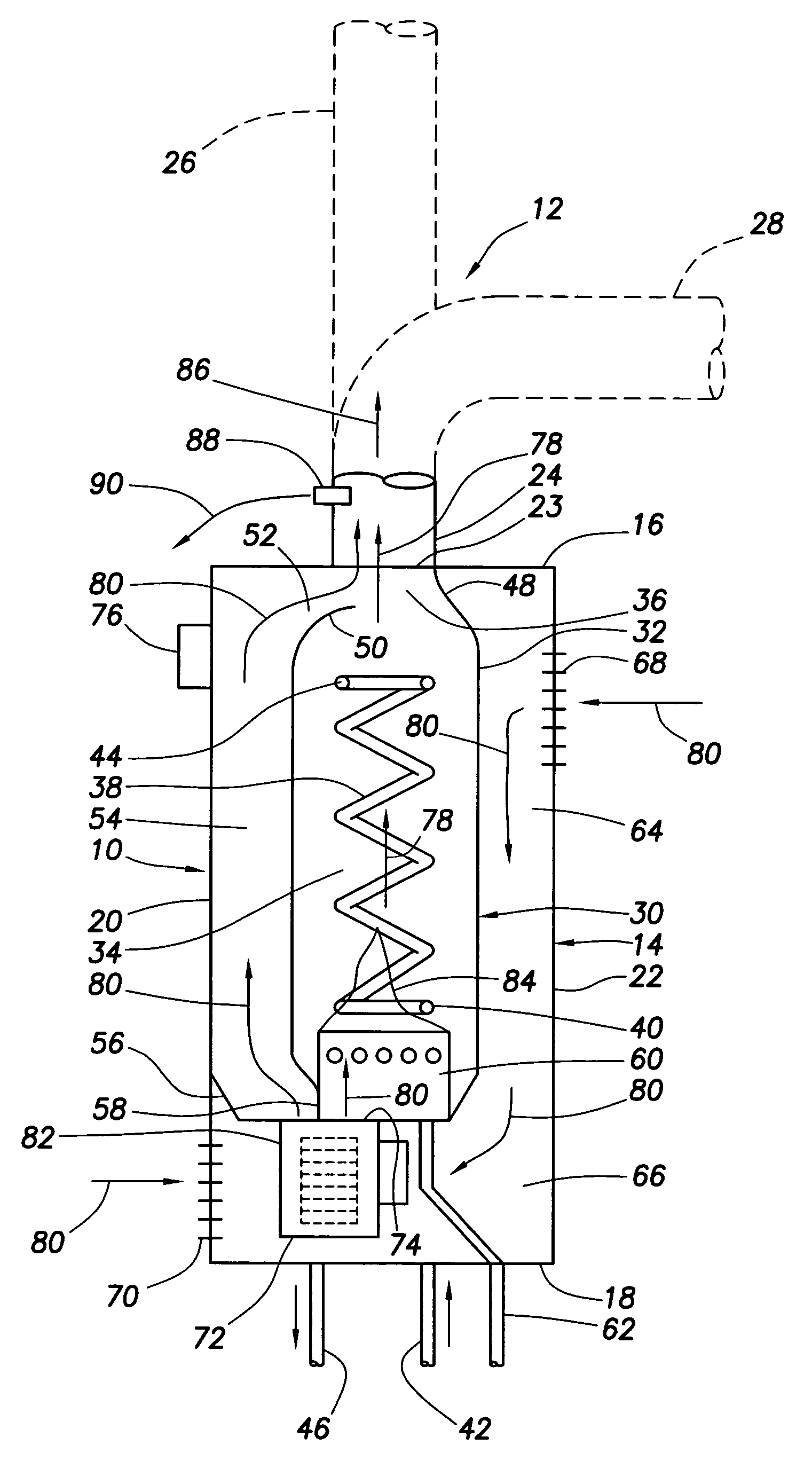
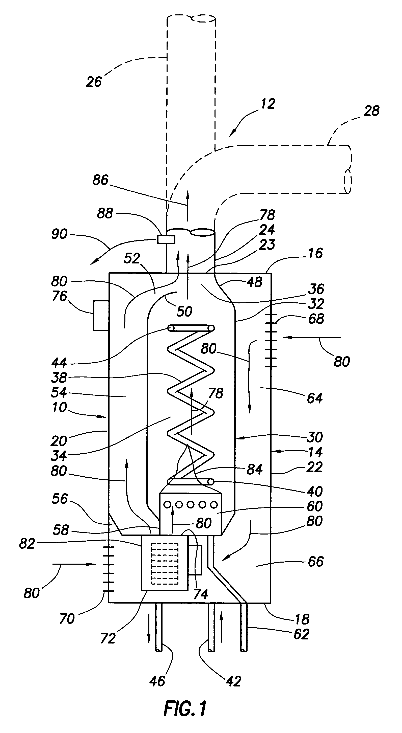
[0014]Schematically depicted in cross-section in FIG. 1 is a fuel-fired instantaneous type water heater 10 that embodies principles of the present invention and is uniquely useable with a low cost plastic vent system 12 as opposed to the conventional and considerably more expensive stainless steel vent system typically required in this water heater application.

[0015]Water heater 10 includes an outer housing 14 having top and bottom end walls 16,18 and opposite vertical wall portions 20,22 extending therebetween. Top end wall 16 has a combustion gas outlet opening 23 therein. The vent system 12, which may representatively be constructed from readily available low cost plastic (DWV-PVC) pipe and associated fittings, illustratively has a vertical inlet portion 24 connected to the top housing end wall 16. From this inlet portion 24, the vent system 12 may extend vertically as indicated by the phantomed flue portion 26, or horizontally as indicated by the phantomed flue portion 28.

[0016]...


PUM


Abstract

An instantaneous type fuel-fired water heater has a variable speed blower that discharges combustion air into a fuel burner utilized to heat water flowing through a heat exchanger portion of the water heater. A portion of the air discharged from the blower bypasses the burner and associated heat exchanger, flows around the heat exchanger, and then mixes with flue gases being discharged from the heat exchanger portion into the flue portion of the water heater. In this manner, such flue gases are cooled by the bypassing blower discharge air to an extent permitting the flue portion to be formed from a low cost plastic material instead of a high temperature metal material such as stainless steel.

Description

BACKGROUND OF THE INVENTION[0001]The present invention generally relates to fuel-fired heating appliances and, in representatively illustrated embodiments thereof, more particularly provides a fuel-fired instantaneous water heater having a special construction that permits it to utilize a low temperature plastic vent structure.[0002]Fuel-fired instantaneous type water heaters have combustion systems designed to heat water as it is being supplied to one or more plumbing fixtures to which it is operatively connected as opposed to heating a stored quantity of water for subsequent delivery to such fixtures. Due to their high flue exhaust temperatures, conventional power vented instantaneous fuel fired water heaters installed indoors have typically had to utilize category III high grade stainless steel (AL-29-4C) vent systems and materials. These necessary stainless steel vent systems, which are usually specified and / or supplied in kit form with the water heater, are expensive, difficult...

Claims


Application Information

Patent Timeline
Patent Type & Authority Patents(United States)
IPC IPC(8): F24D19/00
CPCF24H1/145F24H9/0089
Inventor BOROS, JOZEFTHENAPPAN, SUBBU
Owner RHEEM MFG CO
Why Eureka
Try Eureka