Apparatus and process for removing liquids from drill cuttings

a technology for removing liquids and drill cuttings, applied in the direction of cleaning using liquids, separation processes, borehole/well accessories, etc., can solve the problems of limiting the ability for overboard disposal, difficult to remove wet cuttings, and difficult to clean, etc., to reduce caking

Inactive Publication Date: 2008-03-04
CLEANCUT TECH LTD
View PDF14 Cites 33 Cited by
  • Summary
  • Abstract
  • Description
  • Claims
  • Application Information

AI Technical Summary

Benefits of technology

[0020]The present invention combines direct heating and mechanical mixing of wet and partly dry drill cuttings in a processor, whereby a combination of material ‘conditioning’, conduction heating and direct heating reduce caking and evaporate drilling fluid and other liquids associated with the cuttings.
[0021]By ‘conditioning’ is meant that drier, hotter cuttings present in the processor chamber are back-mixed with newly added wet cuttings. As a consequence, the wetness of the resulting mixture can be reduced to a level that is less likely to cake and / or agglomerate.

Problems solved by technology

Disposal of the wet cuttings is often problematic, as the associated liquids are of environmental concern.
This moisture associated with the cuttings also presents problems in handling and treatment.
Off-shore applications usually require shipping the cuttings to shore for processing or deep well injection, as new regulations limit the ability for overboard disposal.
Land fill disposal has long term environmental liability; composting and bio-remediation methods are time consuming and often require mixing with uncontaminated soil prior to final covering; and the known thermal methods do not address concerns with salt and other contaminants.
An additional issue is the loss of drilling fluid.
The lost fluid results in increased costs to the drilling operator, as do the increased disposal costs.
They are not well adapted for handling changes in cuttings generation rates or varying composition while drilling.
They are also scale limited due to large capital costs.
The previously described caking and agglomeration tendencies of the cuttings are a significant problem in applying these known thermal processes.
The inside of the cake remains wet and is difficult to dry due to this insulating effect.
The operating environment is too lean to support auto-ignition of the vapors.

Method used


Image

  • Apparatus and process for removing liquids from drill cuttings
  • Apparatus and process for removing liquids from drill cuttings
  • Apparatus and process for removing liquids from drill cuttings

Examples


Embodiment Construction

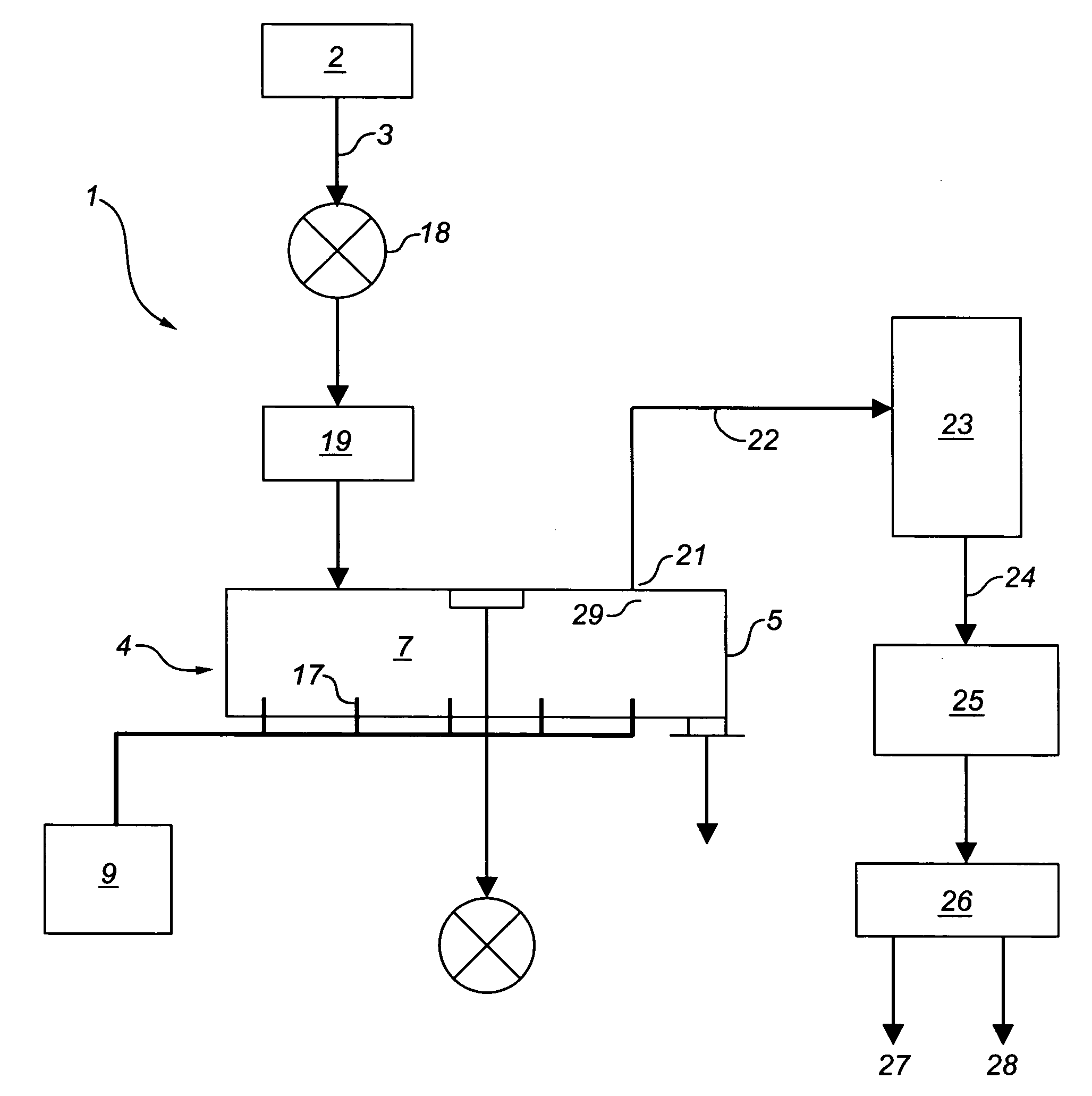
[0048]Having reference to FIG. 7, the illustrated drill cuttings cleaning system 1 may be used in-line with a source 2 of wet cuttings 3, such as an on-going drilling rig operation, from which it directly receives wet drill cuttings 3 from the rig's cuttings / fluid separation assembly. Alternatively the cleaning system 1 may be supplied with cuttings 3 from another source, such as a sump left after drilling has ended. The cuttings 3 may be supplied at a constant or variable rate on a continuous or batch basis.

[0049]In the case of an on-going drilling operation, the drilling fluids are circulated through the borehole to carry drill cuttings from the bottom of the borehole to ground surface while drilling is taking place. It is necessary to remove most of the solid drill cuttings from the drilling fluid to maintain proper fluid properties for hole cleaning and other related concerns such as well bore stability, rate of penetration and formation damage.

[0050]The solid drill cuttings are...


PUM

PropertyMeasurementUnit
temperatureaaaaaaaaaa
densityaaaaaaaaaa
densityaaaaaaaaaa

Abstract

Drill cuttings associated with drilling fluid are thermally cleaned. The wet cuttings are fed into a vessel chamber having mechanical mixers, such as ribbon blenders, extending lengthwise of the chamber. Direct heating is applied to the chamber contents by introducing hot combustion gas from a heater. A combination of direct heating and mechanical back mixing of wet colder cuttings with drier hotter cuttings results in conditioning and conduction heating of the wet cuttings. The drilling fluid is evaporated and removed as gas. Dried cuttings are separately recovered. Caking and agglomeration of the solids is reduced.

Description

CROSS-REFERENCE TO RELATED APPLICATIONS[0001]This application claims priority of U.S. Provisional Patent Application No. 60 / 526,260, entitled “AN APPARATUS AND PROCESS FOR REMOVING LIQUIDS FROM DRILL CUTTINGS”, filed Dec. 1, 2003, which is incorporated herein by reference in its entirety.FIELD OF THE INVENTION[0002]The field of the invention is the thermal removal of associated liquids, such as drilling fluid and water, from drill cuttings generated in the drilling of oil and natural gas wells, with the aim of separately recovering substantially dry cuttings and gases derived from evaporation of the liquids.BACKGROUND OF THE INVENTION[0003]Drilling for oil and gas produces drill cuttings which are brought to ground surface in the circulating drilling fluid. The drill cuttings are substantially separated from the drilling fluid using various combinations of shale shakers, centrifuges and mud tanks. However, some liquid or moisture remains associated with the solid “cuttings” as a sur...

Claims


Application Information

Patent Timeline
Patent Type & Authority Patents(United States)
IPC IPC(8): E21B21/06B01D1/14F26B1/00F26B11/16F26B23/02
CPCE21B21/065F26B1/00F26B11/16F26B23/02Y10S588/90
Inventor MCINTYRE, BARRY E.
Owner CLEANCUT TECH LTD
Why Eureka
Try Eureka