Connector mounting construction and method

a technology of connectors and construction methods, applied in the direction of coupling device connections, printed circuits, coupling device details, etc., can solve the problem of large deviation of proportions from the axis lin

Active Publication Date: 2008-03-04
SUMITOMO WIRING SYST LTD
View PDF7 Cites 7 Cited by
  • Summary
  • Abstract
  • Description
  • Claims
  • Application Information

AI Technical Summary

Benefits of technology

[0011]However, a final operation of the mounting procedure of the connector of the invention is to fasten the fastenable portion to the second member with the fixing member. In this case, the insertion hole of the fastenable portion and the fixing member hole of the second member need to be aligned. It is possible to align the insertion hole and the fixing member hole while moving the connector in a direction intersecting the axis line by utilizing the clearance in the partial locking mechanism, and then to fasten the connector with the screw. In other words, the second end of the connector can be fastened to the second member with the fixing member while the first end of the connector is fit in the fitting hole of the first member in the vertical posture of the connector where the axis line is not deviated from vertical direction. Thus, the action of a bending stress on the connector can be avoided, and the first end of the connector can be prevented from being forcibly fit in the fitting hole.
[0013]The clearance in the insertion hole of the fastenable portion enables a positional displacement between the fitting hole and the fixing member hole and permits a larger deviation of the position of the insertion hole.

Problems solved by technology

Similarly, the position of the insertion hole of the fastenable portion could deviate a large amount from the axis line due to a deformation.

Method used


Image

  • Connector mounting construction and method
  • Connector mounting construction and method
  • Connector mounting construction and method

Examples


Embodiment Construction

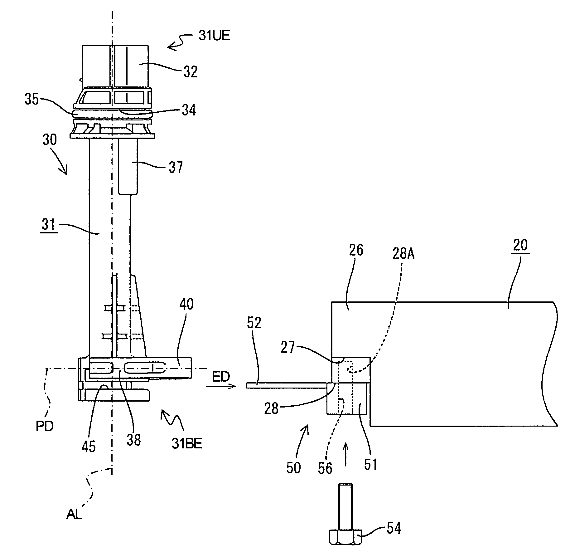
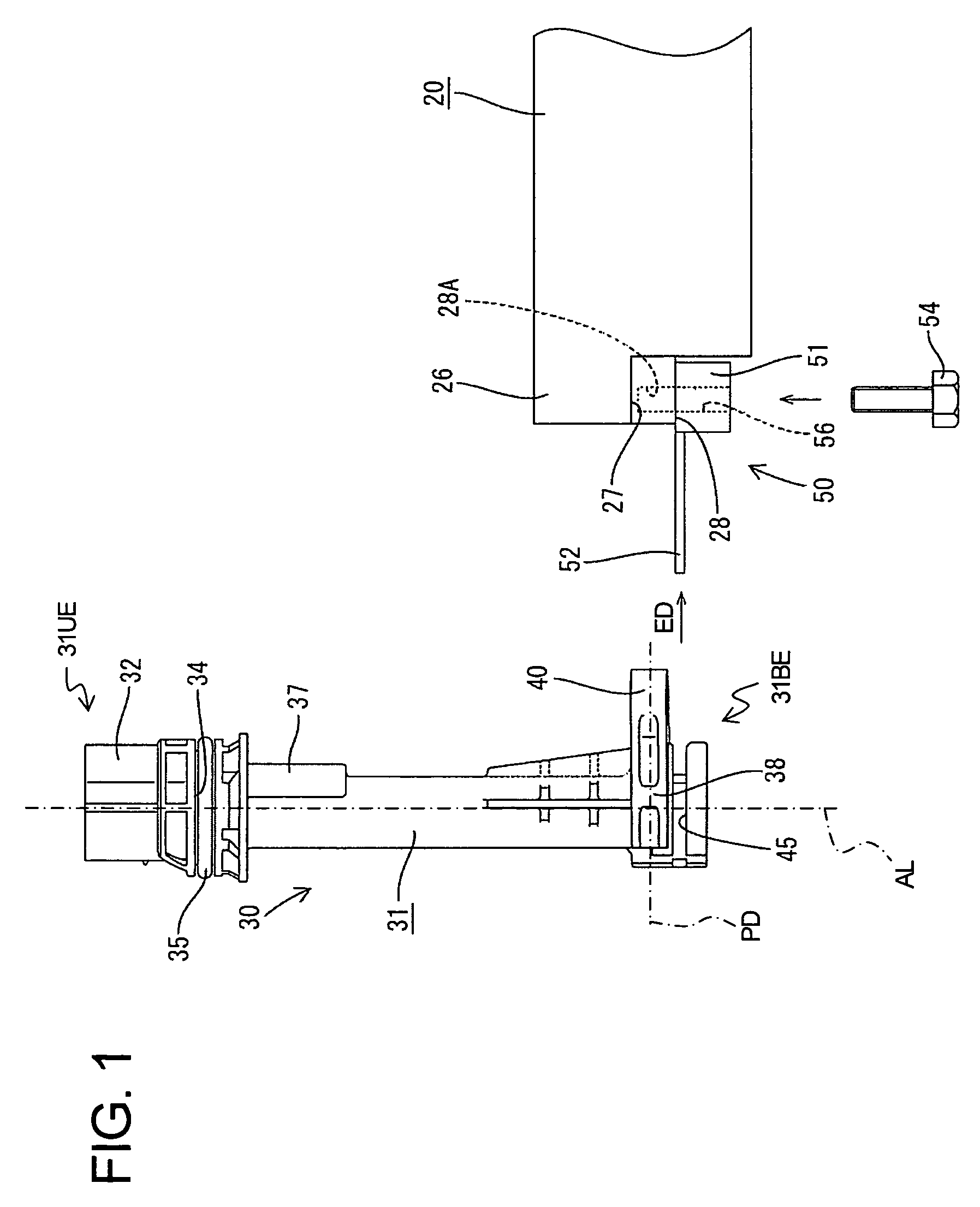
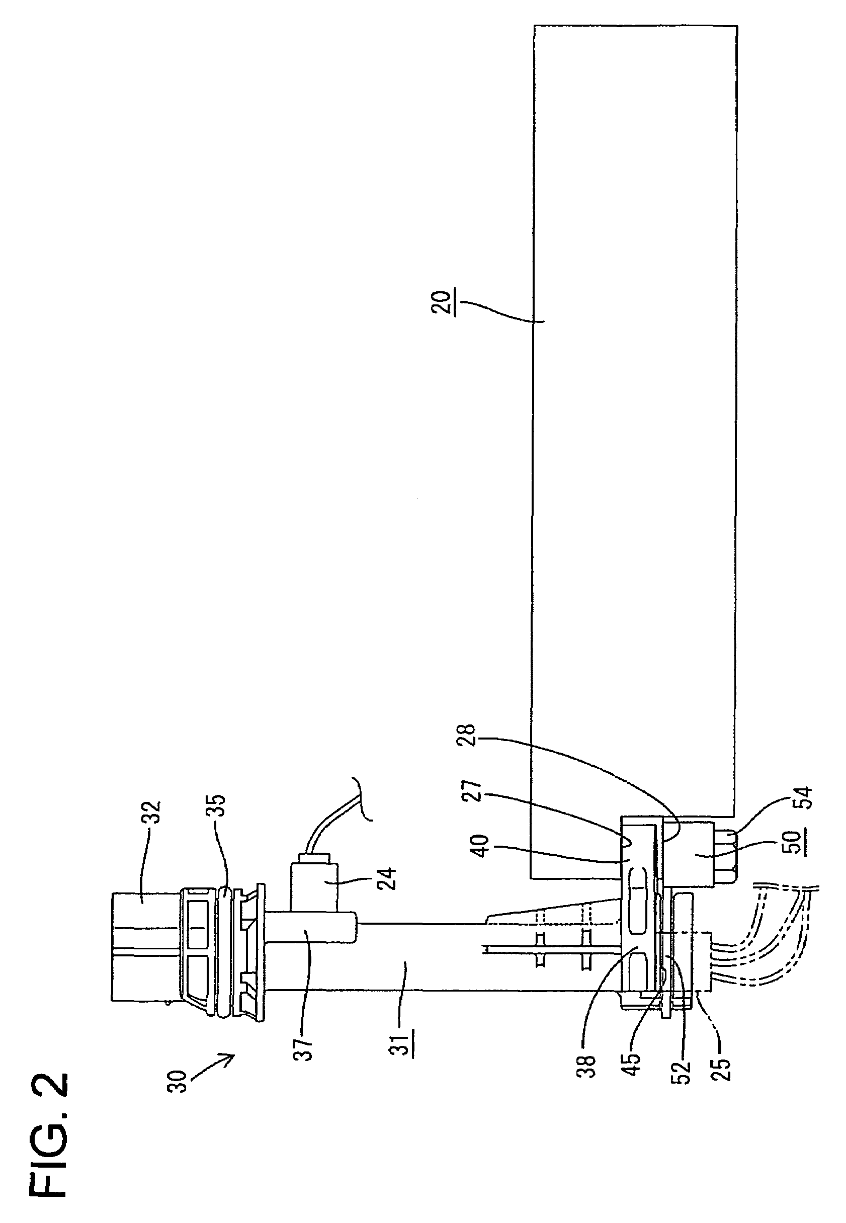
[0029]A construction in accordance with the invention is illustrated in FIGS. 1 to 9 and is used for mounting an intermediate connector 30 to an automatic transmission case 10. The transmission case 10 is made e.g. of a metal or alloy and has an upwardly open pan-shaped main body 11, as shown in FIG. 6. A lid 12, made e.g. of synthetic resin, is mounted over the opening in the main body 11. The lid 12 has a lower portion 13 and an elevated portion 14. The lower portion 13 preferably extends across more than about half of the area of the lid 12 and more preferably about two-thirds of the area of the lid 12 at one side at one side of the lower portion 13. The lower portion 13 is thick and a valve body 20 is mounted on the lower surface of the lower portion 13.

[0030]The valve body 20 is substantially block-shaped and is made e.g. of synthetic resin. Additionally, the valve body 20 is dimensioned to extend across substantially the entire area of the lower portion 13 and slightly into th...


PUM


Abstract

An upper end of a housing (31) is fit into a fitting hole (17) in a lid (12), and a fastenable portion (40) projects horizontally from a bottom end of the housing (31). A bolt (41) is inserted vertically through an insertion hole (42) in the fastenable portion (40) and is screwed into a bolt hole (27A) of a valve body (20) on the lid (12). An engaging groove (45) is formed near the bottom of the housing (31). A U-shaped locking plate (52) projects from the valve body (20) and is inserted into the engaging groove (45) with a clearance that permits movements of the housing (31) along directions intersecting an axis line of the housing (31) while preventing movements of the housing along the axis line. The bolt (41) is insertable into the insertion hole (42) of the fastening portion (40) while defining a clearance.

Description

BACKGROUND OF THE INVENTION[0001]1. Field of the Invention[0002]The invention relates to a construction and a method for mounting a connector in an apparatus or the like.[0003]2. Description of the Related Art[0004]An automatic transmission has a case with a lid that is formed with a connection hole. A body of a solenoid valve is mounted on the lower surface of the lid. U.S. Pat. No. 6,702,593 discloses an intermediate connector that is mounted vertically to the solenoid valve body. More particularly, a fastenable portion projects horizontally from a bottom portion of the intermediate connector and can contact the bottom surface of the solenoid valve body. An insertion hole for a bolt vertically penetrates the fastenable portion, and a seal ring is mounted at an upper end of the intermediate connector. The bolt is inserted through the insertion hole from below and is screwed into a bolt hole in the bottom surface of the valve body to fasten the intermediate connector to the valve bo...

Claims


Application Information

Patent Timeline
Patent Type & Authority Patents(United States)
IPC IPC(8): H05K1/00
CPCH01R13/73H03D7/14H01R13/5202
Inventor MAEGAWA, AKIHITONAGASHIMA, SHINYU
Owner SUMITOMO WIRING SYST LTD
Why Eureka
Try Eureka