Semiconductor device
a technology of semiconductor devices and semiconductors, applied in the direction of semiconductor devices, basic electric elements, electrical appliances, etc., can solve the problems of deteriorating device characteristics of semiconductor devices, affecting the performance of semiconductor devices, so as to improve the solder wettability, prevent bending stress, and improve the effect of solder wettability
- Summary
- Abstract
- Description
- Claims
- Application Information
AI Technical Summary
Benefits of technology
Problems solved by technology
Method used
Image
Examples
first embodiment
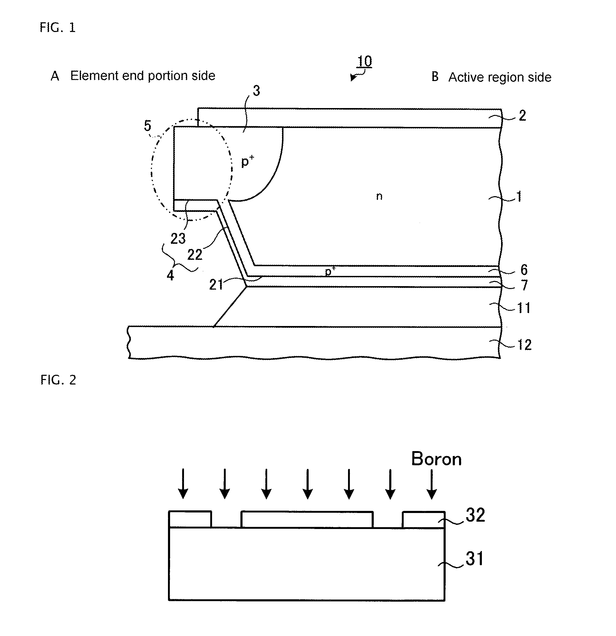
[0091]FIG. 1 is a sectional view showing a main portion of a semiconductor device according to a first embodiment. The semiconductor device shown in FIG. 1 includes semiconductor chip 10, and insulating substrate (a circuit substrate) 12 such as a ceramic insulating substrate (a DBC substrate). A reverse blocking type of semiconductor element having bidirectional voltage resistance characteristics is formed on semiconductor chip 10. Specifically, front surface element structure 2 is provided on the front surface (first main surface) of n-type (first conductivity type) drift region 1 formed from semiconductor chip 10.
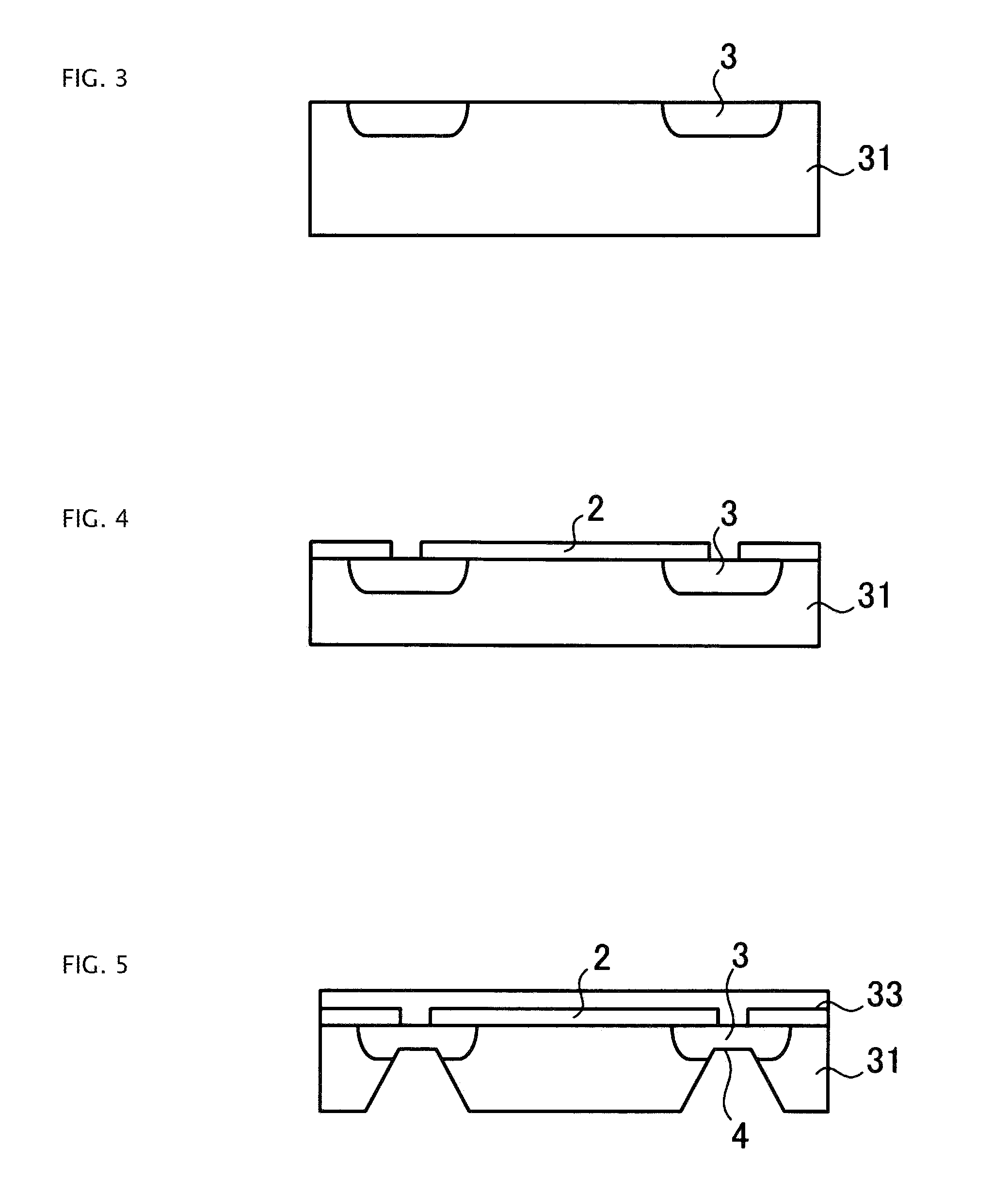
[0092]A metal oxide semiconductor (MOS) gate structure configured of a p+-type base region, an n+-type emitter region, an emitter electrode, a gate electrode, and the like, is provided on an active region side (element central portion side) as front surface element structure 2. Also, a voltage resistant structure configured of a field limiting ring (FLR), which is a floa...
second embodiment
[0112]FIG. 10 is a sectional view showing a main portion of a semiconductor device according to a second embodiment. In the second embodiment, the configuration may be such that collector electrode 7 is not provided on bottom surface 23 of depressed portion 4.
[0113]In the second embodiment, as shown in FIG. 10, collector electrode 47 is provided extending from flat portion 21 of the rear surface of semiconductor chip 40 to side wall 22 of depressed portion 4. That is, collector electrode 47 is not provided on bottom surface 23 or bottom surface 23 corner portion of depressed portion 4. The thickness of collector electrode 47 may be a uniform thickness on both flat portion 21 of the rear surface of semiconductor chip 40 and side wall 22 of depressed portion 4, or the thickness on side wall 22 of depressed portion 4 may become gradually less from an open end portion side to bottom surface 23 corner portion of depressed portion 4. Also, collector electrode 47 may be a multilayer film.
[...
third embodiment
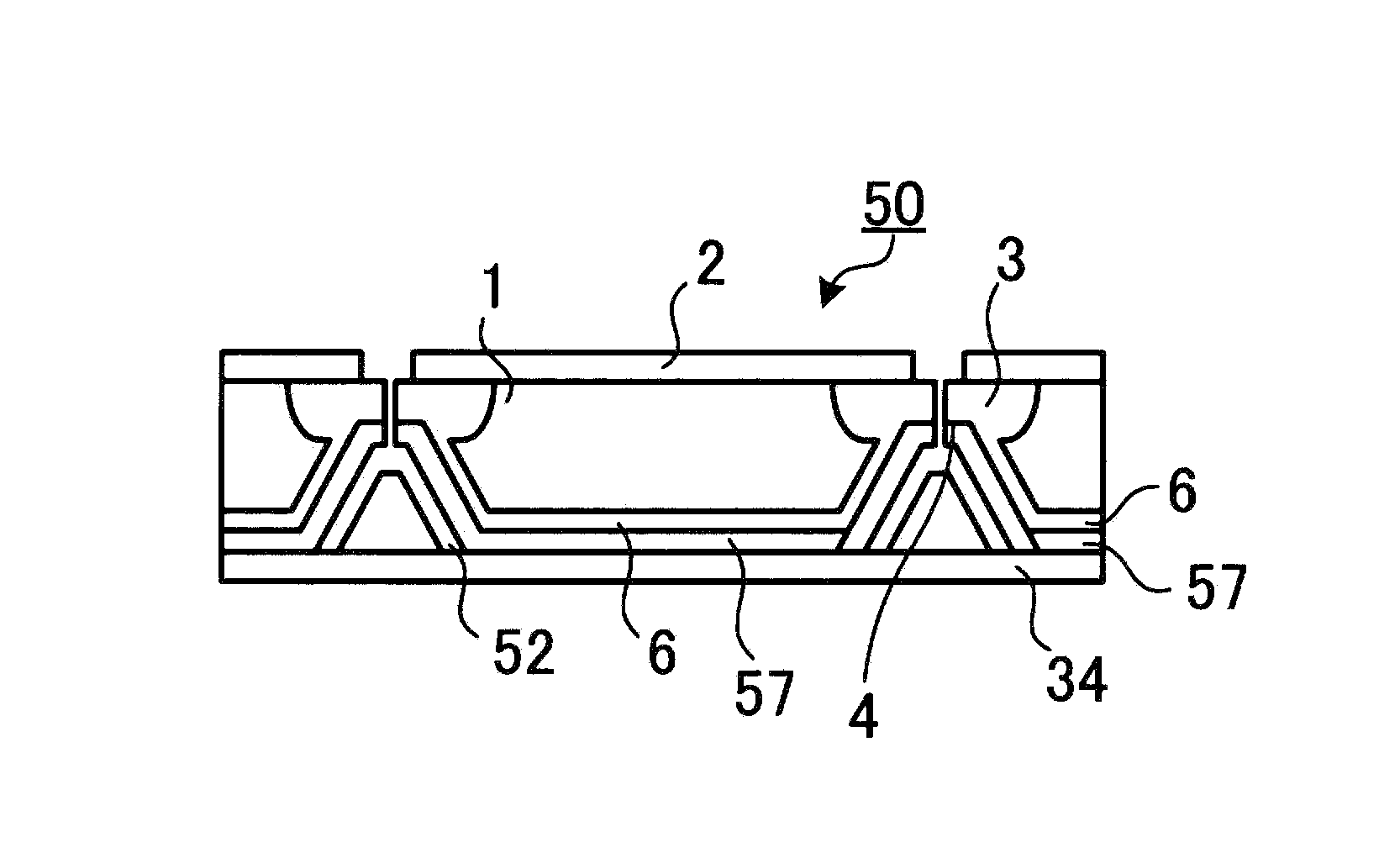
[0120]FIG. 13 is a sectional view showing a main portion of a semiconductor device according to a third embodiment. In the first embodiment, a configuration may be such that the collector electrode provided on side wall 22 and bottom surface 23 of depressed portion 4 is covered with a polyimide resin film.
[0121]In the third embodiment, as shown in FIG. 13, collector electrode 57 is provided extending from flat portion 21 of the rear surface of semiconductor chip 50 to bottom surface 23 of depressed portion 4. The thickness of collector electrode 57 may be a uniform thickness from flat portion 21 of the rear surface of semiconductor chip 50 to bottom surface 23 of depressed portion 4. Also, collector electrode 57 may be a multilayer film. Collector electrode 57 on side wall 22 and bottom surface 23 of depressed portion 4 is covered with film 52 formed from a material with poor solder wettability. Film 52 formed from a material with poor solder wettability may be, for example, a polyi...
PUM
 Abstract
Description
Claims
Application Information
 - R&D
- Intellectual Property
- Life Sciences
- Materials
- Tech Scout
- Unparalleled Data Quality
- Higher Quality Content
- 60% Fewer Hallucinations
Browse by: Latest US Patents, China's latest patents, Technical Efficacy Thesaurus, Application Domain, Technology Topic, Popular Technical Reports.
© 2025 PatSnap. All rights reserved.Legal|Privacy policy|Modern Slavery Act Transparency Statement|Sitemap|About US| Contact US: help@patsnap.com


