Semiconductor device and its manufacturing method

a technology of semiconductors and semiconductors, applied in semiconductor devices, electrical equipment, transistors, etc., can solve the problems of dielectric breakdown field strength, high blocking voltage voltage power devices, and silicon carbide substrate-based mosfets with about one-tenth the channel mobility of silicon substrate-based mosfets

Active Publication Date: 2008-03-04
NAT INST OF ADVANCED IND SCI & TECH
View PDF13 Cites 36 Cited by
  • Summary
  • Abstract
  • Description
  • Claims
  • Application Information

AI Technical Summary

Benefits of technology

[0014]A method of manufacturing a semiconductor device according to a first aspect of the invention comprises the steps of forming a gate insulation layer on a semiconductor region formed of silicon carbide having a (000-1) face orientation, forming a gate electrode on the gate insulation layer, forming an electrode on the semiconductor region, and cleaning a surface of the semiconductor region, wherein the gate insulation layer is formed in an atmosphere containing 1% or more H2O (water) vapor at a temperature of from 800° C. to 1150° C. to reduce an interface trap density of an interface between the gate insulation layer and the semiconductor region. Oxidizing a region of (000-1) face silicon carbide on a semiconductor substrate in an atmosphere containing 1% or more H2O vapor enables channel mobility to be improved.
[0015]In a second aspect of the invention in relation to the first aspect, the interface trap density of the interface between the gate insulation layer and the semiconductor region can be further reduced by forming the gate insulation layer in an atmosphere containing water vapor at a temperature of from 800° C. to 1050° C. The interface trap density can be reduced, enabling the channel mobility to be improved by thus limiting the temperature at which the gate insulation layer is oxidized on the (000-1) face silicon carbide region to 800° C. to 1050° C.
[0016]A method of manufacturing a semiconductor device according to a third aspect of the invention comprises the steps of forming a gate insulation layer on a semiconductor region formed of silicon carbide having a (000-1) face orientation, forming a gate electrode on the gate insulation layer, forming an electrode on the semiconductor region, cleaning a surface of the semiconductor region, wherein the step of forming the gate insulation layer is followed by heat treatment in an atmosphere containing H2 (hydrogen) gas or H2O (water) vapor to reduce an interface trap density of an interface between the gate insulation layer and the semiconductor region. Channel mobility can thus be improved by following the forming of the gate insulation layer on the (000-1) face silicon carbide region of the substrate by heat treatment in an atmosphere containing H2 or H2O at a concentration of from 1% to 100%.

Problems solved by technology

This gives rise to the problem that a silicon carbide substrate-based MOSFET has about one-tenth the channel mobility of a silicon substrate-based MOSFET.
However, the (11-20) face has lower dielectric breakdown field strength than the (0001) or (000-1) face, and is therefore disadvantageous for high-voltage-resistancehigh blocking voltage voltage power devices.
The channel doping technology is not suitable for high-voltage-resistancehigh blocking voltageblocking voltage power devices, because although it improves channel mobility, leakage current flows more readily and voltage resistanceblocldng voltage decreases.
Moreover, a temperature of 1000° C. is too high, with the oxidation layer being reduced by the hydrogen, degrading the reliability of a device in which the oxidation layer is used as a gate layer.
Also, the heat treatment temperature within the range 300° C. to 500° C. is too low for adequate heat-treatment.
Also, the described mixture ratio of hydrogen and oxygen used in the pyrogenic method is not optimal.
However, the (11-20) face has lower dielectric breakdown field strength than the (0001) or (000-1) face, and is therefore disadvantageous for high-voltage-resistancehigh blocking voltage power devices.
Channel doping is not suitable for high-voltage-resistancehigh blocking voltage power devices, because although it improves channel mobility, it causes leakage current to flow more readily, so voltage resistanceblocking voltage decreases.

Method used


Image

  • Semiconductor device and its manufacturing method
  • Semiconductor device and its manufacturing method
  • Semiconductor device and its manufacturing method

Examples


Embodiment Construction

[0072]The present invention provides a semiconductor device and method of manufacturing same, in which the focus is on a technology for forming an oxide layer / silicon carbide interface in the (000-1) face, which has higher dielectric breakdown field strength than the (11-20) face and higher channel mobility than the (0001) face. The embodiments of the present invention will now be described in detail with reference to the drawings.

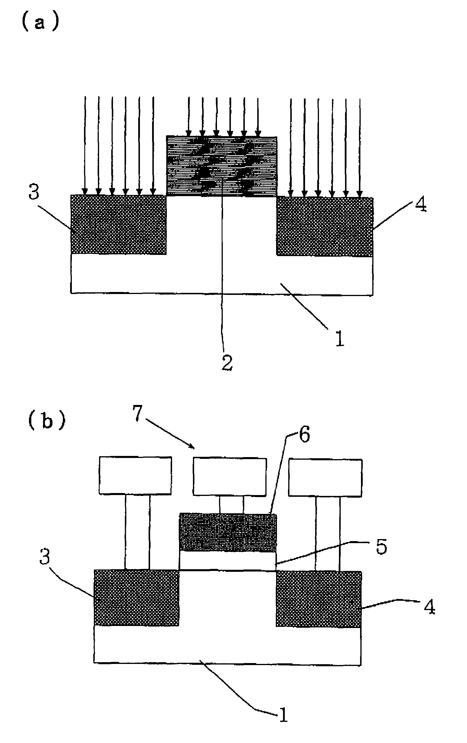
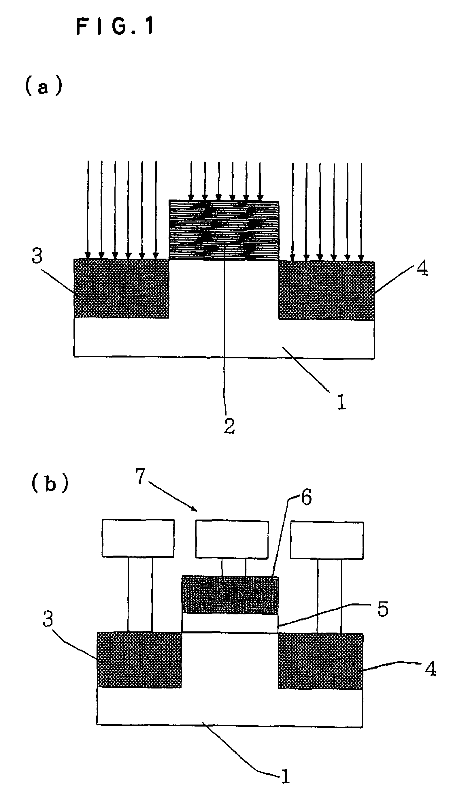
[0073]A specific example of the method of manufacturing a semiconductor device will be described with reference to FIG. 1.

[0074]FIG. 1 is a cross-sectional view of the process of fabricating a MOS transistor using a silicon carbide substrate, shown partway through the fabrication procedure. FIG. 1(a) shows a (000-1)-faced p-type silicon carbide substrate 1 (4H—SiC, impurity concentration of 5×1015 cm−3) on which RIE (reactive ion etching) has been used to form photolithography alignment marks, following standard RCA cleaning. It is also possible to use, as...


PUM


Abstract

A semiconductor device and a method of manufacturing the device using a (000-1)-faced silicon carbide substrate are provided. A SiC semiconductor device having a high voltage resistancehigh blocking voltage and high channel mobility is manufactured by optimizing the heat-treatment method used following the gate oxidation. The method of manufacturing a semiconductor device includes the steps of forming a gate insulation layer on a semiconductor region formed of silicon carbide having a (000-1) face orientation, forming a gate electrode on the gate insulation layer, forming an electrode on the semiconductor region, cleaning the semiconductor region surface. The gate insulation layer is formed in an atmosphere containing 1% or more H2O (water) vapor at a temperature of from 800° C. to 1150° C. to reduce the interface trap density of the interface between the gate insulation layer and the semiconductor region.

Description

FIELD OF THE INVENTION[0001]The present invention relates to a semiconductor device and to a method of manufacturing the semiconductor device on a silicon carbide substrate having a prescribed crystal plane orientation. It particularly relates to a semiconductor device that uses a gate insulation layer, such as those of a metal-oxide-semiconductor (MOS) capacitor or a MOS field-effect transistor (MOSFET), and to a method of manufacturing the semiconductor device.BACKGROUND ART[0002]The interface trap density of an oxide layer-silicon carbide interface using a silicon carbide (SiC) substrate is some ten times higher than that of a silicon MOS transistor. This gives rise to the problem that a silicon carbide substrate-based MOSFET has about one-tenth the channel mobility of a silicon substrate-based MOSFET. Although a bulk SiC substrate having the crystal structure referred to as 4H—SiC has about twice the channel mobility of a bulk SiC substrate having the crystal structure referred ...

Claims


Application Information

Patent Timeline
Patent Type & Authority Patents(United States)
IPC IPC(8): H01L21/336H01L21/31H01L21/469H01L21/04H01L27/092
CPCH01L21/049H01L27/092H01L29/045H01L29/1608H01L29/66068H01L29/7395H01L29/7802H01L29/7835H01L21/8213H01L29/6606H01L29/94
Inventor FUKUDA, KENJISENZAKI, JUNJI
Owner NAT INST OF ADVANCED IND SCI & TECH
Why Eureka
Try Eureka