Multi-layered radiant thermal evaporator and method of use

a technology of radiant thermal evaporator and evaporator chamber, which is applied in the direction of lighting and heating apparatus, separation process, furnace, etc., can solve the problems of high deposition rate, long run time, and the need to heat the entire quantity of coating material in the crucible, and achieve reliable and constant heat source, high quality usefulness, and non-corrosion

Inactive Publication Date: 2008-03-04
DARLY CUSTOM TECH
View PDF10 Cites 17 Cited by
  • Summary
  • Abstract
  • Description
  • Claims
  • Application Information

AI Technical Summary

Benefits of technology

[0020]Another advantage of the present invention is the heat source is manufactured from a ceramic or intermetallic material that provides a reliable and constant heat source that is non-corrosive with most coating materials and / or reaction gases resulting in high quality usefulness over a long period.
[0021]Another advantage of the evaporator of the present invention is that it provides heat at a constant temperature and a constant distance from the surface of a coating material in a crucible throughout the duration of an evaporation process thereby providing uniform coatings over an entire substrate.

Problems solved by technology

Wire feed thermal evaporation systems are efficient and operate at relatively high line speeds with high deposition rates and long run times, however, are generally limited to one type of a source material.
One major drawback of this type of system is that the entire quantity of the coating material in the crucible must be heated to a boiling temperature before the coating process can begin.
Also, an evaporation process is often limited by the capacity of the crucible.
Accordingly, major drawbacks of many induction heater systems include long heat-up and cool-down times and limited material supplies causing reduced deposition rates, line speeds and overall throughput of a coating process.
Additionally, induction heating systems wherein a coating material is heated from the sides or bottom of a crucible can have a tendency to blow out vapor from the interior of the crucible causing undesirable splashing or splattering at the surface of the coating material in the crucible.
The comparatively high cost of this type of electron beam system drastically limits its usefulness in the economical production of coated materials.
Additionally, many prior art thermal heating elements are made from expensive metals such as molybdenum, tungsten or tantalum which can be easily corroded or damaged by contacting coating materials and / or reaction gases like nitrogen and oxygen which may be added to a coating process for forming an oxide or nitride film on a substrate or for assisting the reaction process.

Method used


Image

  • Multi-layered radiant thermal evaporator and method of use
  • Multi-layered radiant thermal evaporator and method of use
  • Multi-layered radiant thermal evaporator and method of use

Examples


Embodiment Construction

[0052]Following is a detailed description of the embodiments of the present invention that are illustrated in the drawings wherein like structures are identified with like reference designations.

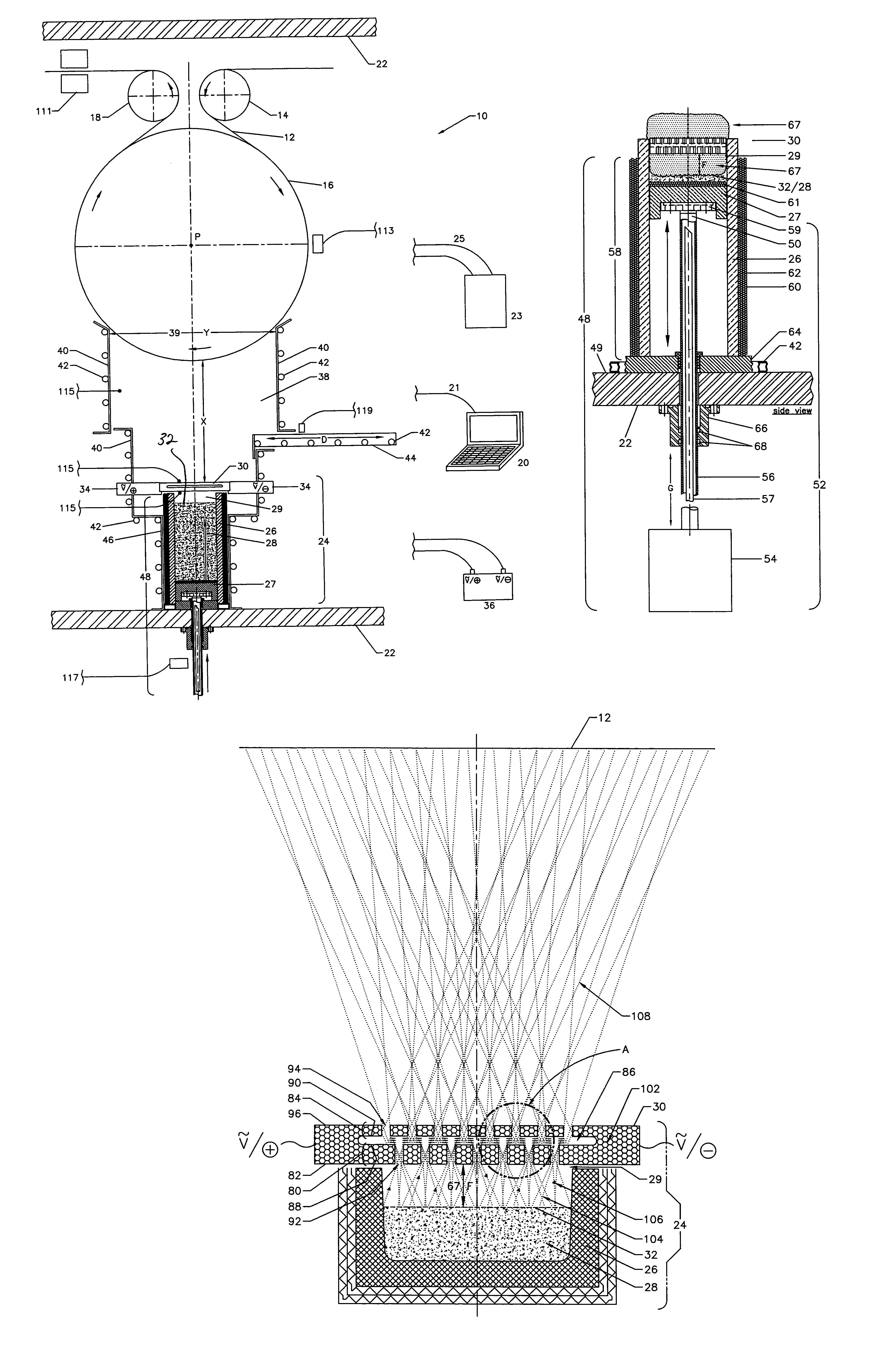
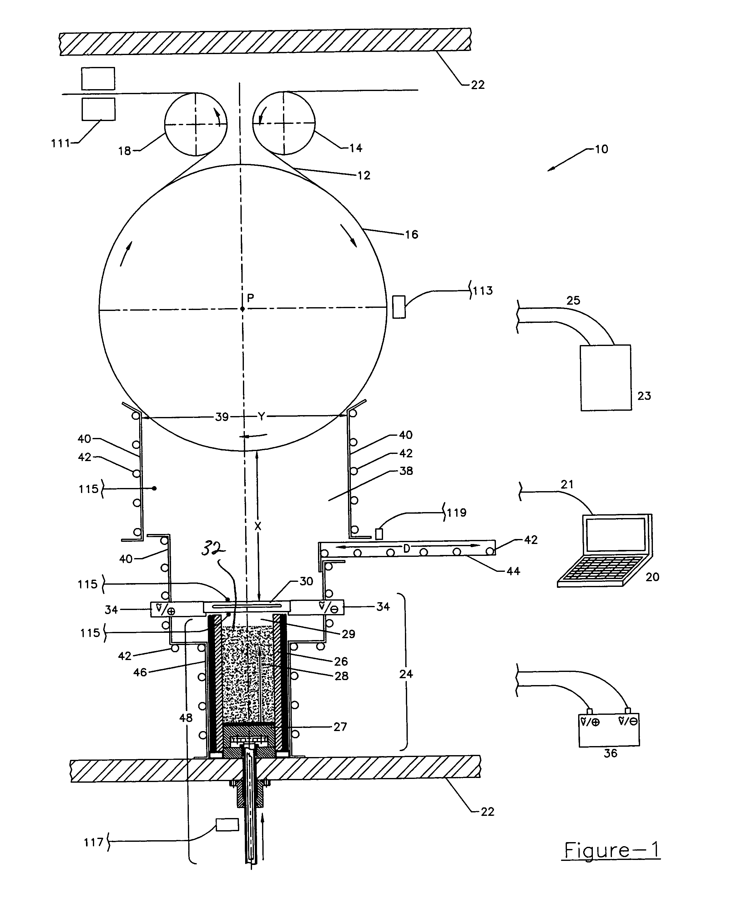
[0053]As shown in FIG. 1, the present invention is directed to a system generally designated by the reference numeral 10, for coating a substrate by evaporating or sublimating a coating material in a vacuum. In the FIG. 1 embodiment, a substrate 12 to be coated is a semi-continuous or continuous web carried on a feeder roll 14, a process roll 16 and a take-up roll 18. At least one of the feeder roll 14, process roll 16 and take-up roll 18 are coupled to a drive mechanism (not shown) for controlling the movement of the substrate 12. The drive mechanism or substrate driver may be coupled to a controller 20 for controlling the rotational velocity or a line speed of the process roll 16. In operation, the line speed of the process roll can be in excess of 120 feet per minute depending on the appl...


PUM

PropertyMeasurementUnit
distanceaaaaaaaaaa
thicknessaaaaaaaaaa
heataaaaaaaaaa

Abstract

The present invention provides a system and method for uniform coating of a substrate at high deposition rates by evaporating a coating material in a vacuum chamber. The system includes an evaporator having a heating crucible for containing a coating material to be evaporated and a generally planar heat source disposed so as to heat a surface of a coating material contained in the heating crucible. Preferably, the heat source is manufactured from a ceramic or intermetallic material and includes a first layer defining a first set of openings and a second layer defining a second set of openings wherein the second layer overlies the first layer and is spaced apart therefrom. The first and second sets of openings allow the evaporated coating material to pass therethrough for dispersion of the coating material in a deposition zone defined by a containment shield disposed above the heat source.

Description

FIELD OF THE INVENTION[0001]The present invention generally relates to thermal sublimation processes and equipment and more particularly to a system and method for applying a coating to a substrate including an evaporator having a heat source disposed above a crucible containing a coating material wherein the heat source includes a ceramic or intermetallic material.BACKGROUND OF THE INVENTION[0002]Thermal sublimation and deposition of materials on a substrate in a vacuum is known and in increased demand especially for deposition of materials having high melting temperatures on continuous webs. Several prior art techniques are commonly used for thermal evaporation of coating materials wherein a coating material is heated to a melting temperature within a vacuum chamber creating a vapor and the vapor condenses on a cooler substrate forming a coating on the substrate. Prior art thermal evaporation systems include aluminum wire feed systems, induction heaters and heating systems having ...

Claims


Application Information

Patent Timeline
Patent Type & Authority Patents(United States)
IPC IPC(8): H05B3/30C23C14/26C23C14/56F27B14/04F27B14/06F27B14/14C23C14/24C23C16/00
CPCC23C14/243C23C14/246C23C14/26C23C14/56C23C14/562
Inventor YANG, YIMOUMARTIN, KENNETHMISUNAS, STANLEY J.TAO, SONGMORGANSON, DAVID
Owner DARLY CUSTOM TECH
Why Eureka
Try Eureka