
Radiation detector head

a detector head and detector technology, applied in the field of radiation detection, can solve the problems of inability to fit side-by-side into the base board, prohibitive cost of such a camera head, etc., and achieve the effect of reducing the deformation of images acquired and constant pixel pitch

Inactive Publication Date: 2008-03-04
ORBOTECH LTD
View PDF7 Cites 35 Cited by
  • Summary
  • Abstract
  • Description
  • Claims
  • Application Information

AI Technical Summary

Benefits of technology

The present invention provides a new radiation camera head with a constant pitch between pixels over the whole camera head, even though the detector modules have production tolerances. The head uses a collimator with multiple holes, and the gaps between modules are designed to compensate for the differences in production tolerances. The head also includes an array of pixelated detector modules with insulated conductive bands to improve sensitivity. The detector modules have side walls with reduced sensitivity, but the insulated conductive bands compensate for the reduced sensitivity. The head allows for easy removal and replacement of modules without interfering with the others. The constant pitch between pixels is important to avoid deformation of the acquired image. The head is designed to improve detection sensitivity and minimize detection loss caused by dead areas in the array.

Problems solved by technology

However, normal production techniques are such that the module dimensional tolerances, and those of the assembly components by means of which they are mounted onto the electronic base board in the camera head, may result in either unacceptable gaps between neighboring modules, or conversely, interference between the adjacent edges of the modules, such that they cannot even be fitted into the base board side-by-side.
Production of the modules with such tight tolerances that they would all fit together “perfectly” would make the cost of such a camera head prohibitive.

Method used


Image

  • Radiation detector head
  • Radiation detector head
  • Radiation detector head

Examples


Embodiment Construction

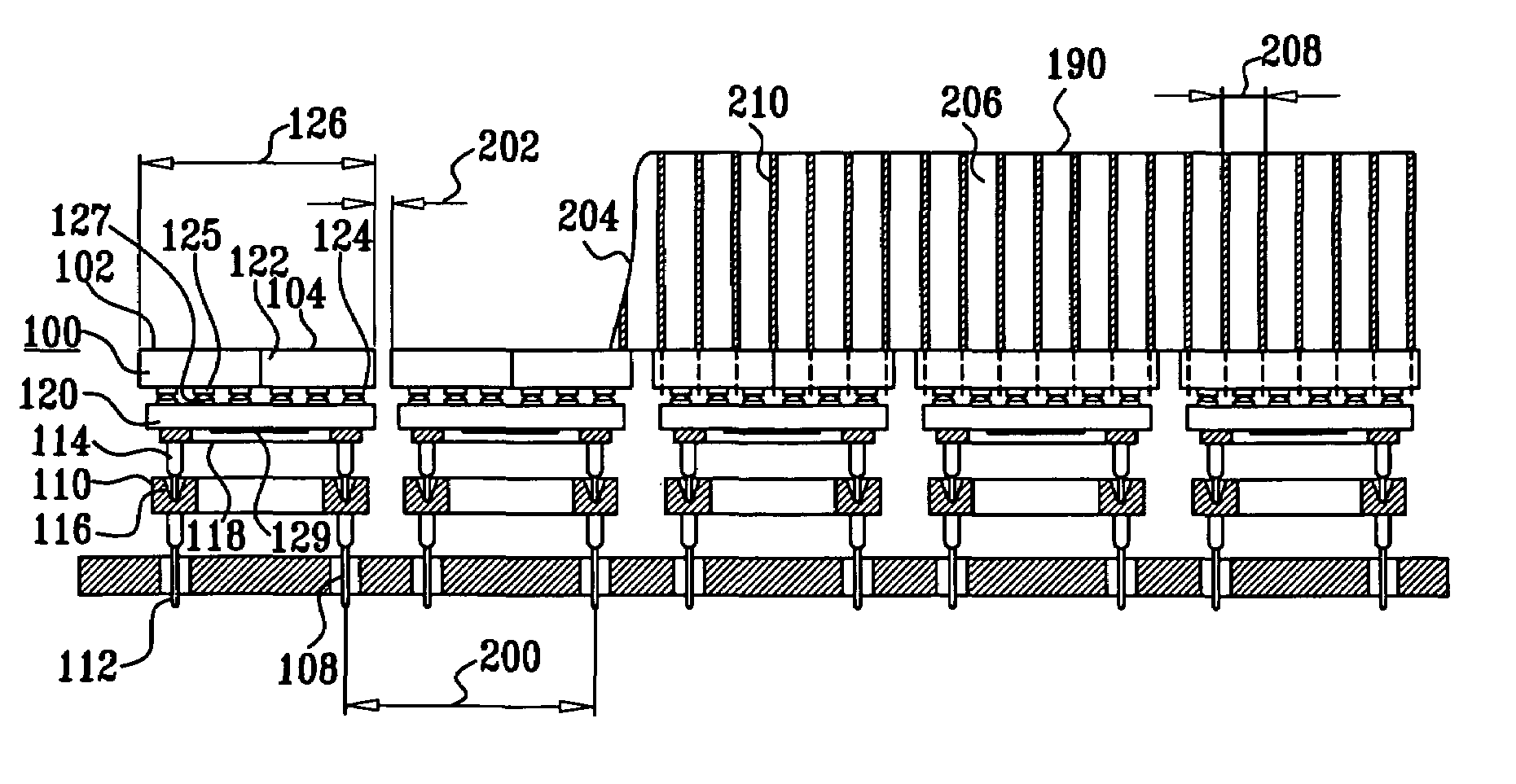
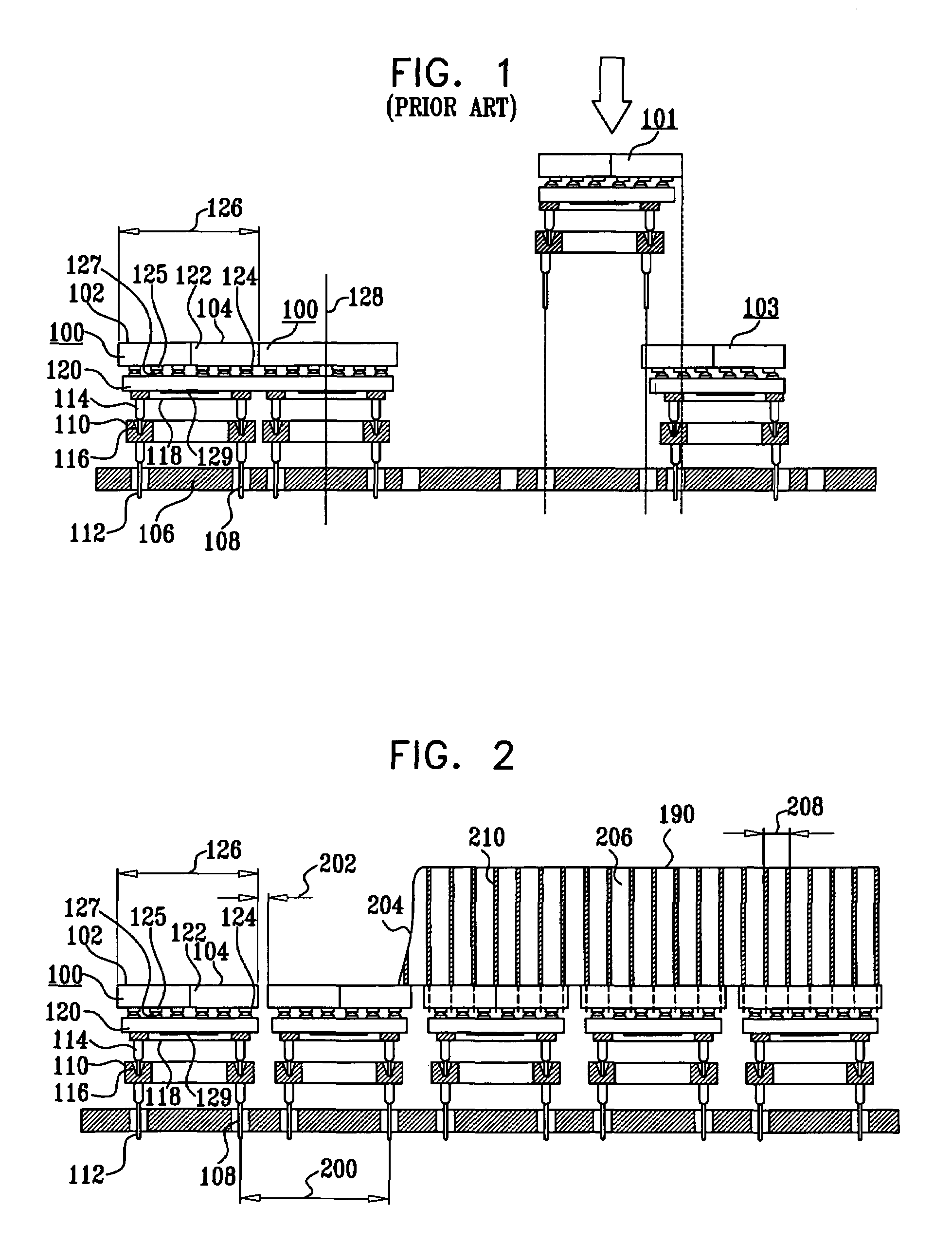
[0033]Reference is now made to FIG. 1 which is a schematic cross-sectional illustration from the side of a prior-art detector array constructed according to conventional Z-technology. According to this technology, individual detector modules 100 are tiled by a butting process, to form a focal plane array 102 of cathodes 104. The tiling of modules 100 is preferably achieved by mounting the modules on a Detector Carrier Board (DCB) 106. The DCB 106 is generally made of Printed Circuit Board (PCB) and may include mounting holes 108 either for direct mounting of the modules 100, or alternatively for receiving the pins 112 of mounting sockets 110. Modules 100 are preferably mounted on sockets 110 by inserting their Pin Grid Array (PGA) 114 into mounting holes 116 of sockets 110. PGA 114 is arranged along a further PGA frame 118. PGA frame 118 is attached to carrying plate 120, to which a detector or detectors 122 are bonded by conductive glue 124. The conductive glue 124 electrically and...


PUM


Abstract

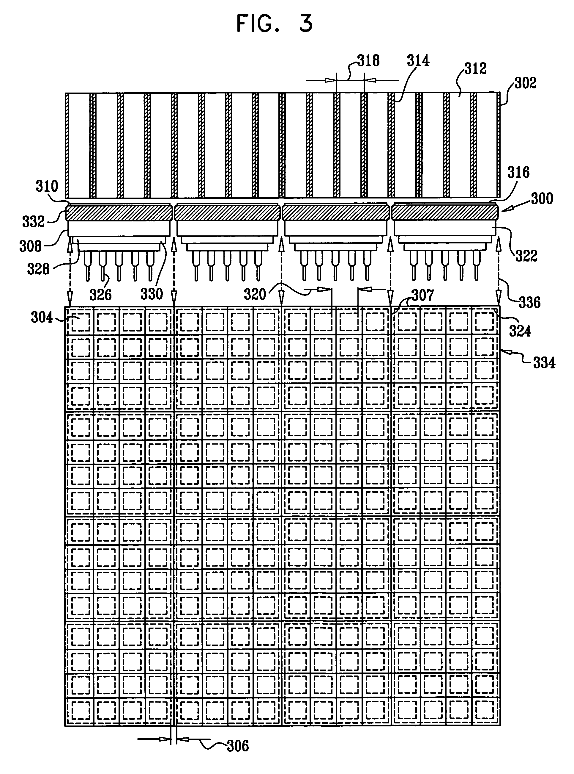
A radiation detection camera head having a focal-plane array of pixelated detectors having constant pitch between pixels over the whole of the camera head, while using detector modules having normal production tolerances, and which can nevertheless be readily removed and replaced in the detector array by means of predetermined gaps between adjacent detector modules. The pixels on the side walls of the detector modules have reduced size to maintain constant pitch over the array in spite of production variation between modules. The reduction in sensitivity due to this reduced size is compensated for by the addition of insulated conductive bands on the side walls. The head collimator is such that the septa fall between pixels and between modules, such that head sensitivity is maintained at its optimum value.

Description

CROSS-REFERENCE TO RELATED APPLICATIONS[0001]This application claims the benefit of U.S. Provisional Patent Application 60 / 588,191, filed Jul. 14, 2004, which is assigned to the assignee of the present patent application, and whose disclosure is incorporated herein by reference.FIELD OF THE INVENTION[0002]The present invention relates to the field of radiation detection, and in particular to the field of X-ray and Gamma ray detection and imaging cameras.BACKGROUND OF THE INVENTION[0003]Solid-state cameras are capable of acquiring high quality images due to their good energy resolution and their high spatial resolution. The energy resolution is mainly dependent on the intrinsic physical properties of the materials from which the detectors of the camera head are made. Such materials are generally various types of semiconductors, such as, CdTe, CdZnTe, Si, GaAs, Ge, InGaAs, and AlGaAs. On the other hand, the spatial resolution of solid-state cameras is mainly dependent on the geometric...

Claims


Application Information

Patent Timeline
Patent Type & Authority Patents(United States)
IPC IPC(8): G01T1/24H04N25/00
CPCG01T1/2928G01T1/243
Inventor EL-HANANY, URISHAHAR, ARIETSIGELMAN, ALEX
Owner ORBOTECH LTD
Learn More