Fuel injectors with integral fiber optic pressure sensors and associated compensation and status monitoring devices

a fuel injector and fiber optic technology, applied in the direction of fluid pressure measurement, machine/engine, optical radiation measurement, etc., can solve the problems of difficult and expensive manufacture of gasoline injectors, and achieve accurate and cost-effective fuel injectors, accurate and repeatable spray patterns, and low cost

Inactive Publication Date: 2008-03-04
WLODARCZYK MAREK T +1
View PDF14 Cites 61 Cited by
  • Summary
  • Abstract
  • Description
  • Claims
  • Application Information

AI Technical Summary

Benefits of technology

[0003]A key component that is required for both Direct Diesel Injected (DDI) and Direct Gasoline Injected (DGI) engines is an accurate and cost-effective fuel injector. In diesel engines, the new injection must operate at extremely high pressures (as high as 30,000 psi), provide accurate and repeatable spray patterns, and be precisely timed. In addition, such an injector must operate for as many as 0.5 million miles and be of low cost.
[0005]To provide the required performance, reliability, and low-cost for both DDI and DGI injectors, disclosed below are approaches based on closed loop control of injector operating parameters, where combustion chamber and fuel pressures are used as control parameters. As detailed below a preferred way of obtaining these two pressures is to integrate two miniature fiber optic pressure sensors inside an injector. Such a “smart” injector does not need to be individually calibrated, as currently done, so its price can be significantly lower. Differences caused by manufacturing variability, aging, pressure line fluctuations, or fuel quality can be compensated for by using closed-loop control of fuel injection timing, duration and pressure. The combustion chamber pressure sensor of the smart injector provides, in addition, real-time information about cylinder pressure including peak pressure (PP), indicated mean effective pressure (IMEP), start of combustion (SOC) and location of peak pressure (LPP). When inputs from both fuel and combustion pressure sensors are used to control the injector, simultaneous benefits of reduced emissions, improved fuel economy, increased injector reliability, and reduced cost can be achieved.Invention Overview
[0006]The fiber optic sensors utilized in the smart injector are of a novel construction aimed at high accuracy in a very small device exposed to extremely high pressures and temperatures. The sensor tip may be as small as 2.5 mm in diameter or smaller. By using a specially shaped diaphragm in the sensor and two D-shaped optical fibers, high levels of optical modulation can be realized at small diaphragm deflections. Small diaphragm deflections are required to permit high diaphragm yield strength and long fatigue life. Using a two photodiode detection technique, each sensor's signal interface / conditioner can operate accurately over a temperature range of −50 to 150° C.

Problems solved by technology

In DGI applications, in particular, the very poor lubricating nature of gasoline and critical injector specifications make gasoline injectors difficult and expensive to manufacture.

Method used


Image

  • Fuel injectors with integral fiber optic pressure sensors and associated compensation and status monitoring devices
  • Fuel injectors with integral fiber optic pressure sensors and associated compensation and status monitoring devices
  • Fuel injectors with integral fiber optic pressure sensors and associated compensation and status monitoring devices

Examples


Embodiment Construction

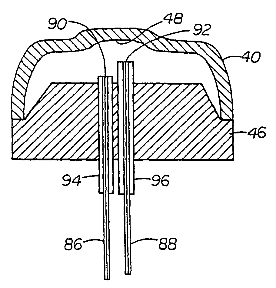
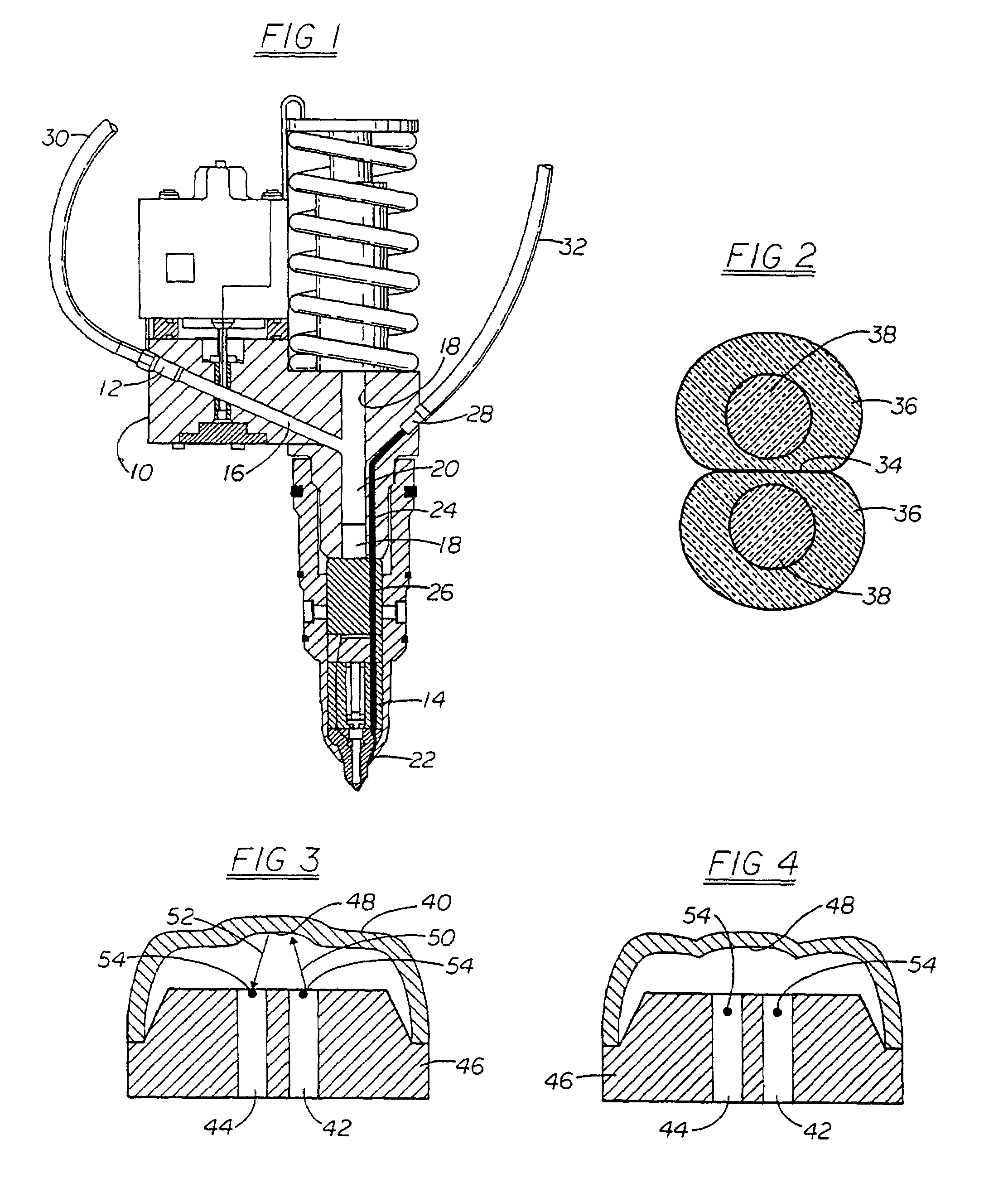
[0029]In FIG. 1 the modified smart injector 10 is fitted with both a fuel pressure sensor 12 and a combustion pressure sensor 14. The fuel sensor 12 may be mounted in a modified existing injector opening 16 as shown. The opening 16 comprises a channel communicating with the axial fuel channel 18 of the injector 10. The sensor 12 may be approximately 5 mm in diameter and threaded into the channel 16 whereby the sensor diaphragm is directly exposed to the fuel pressure in the channel and also the axial fuel channel 18 when the injector plunger 20 is retracted.

[0030]The combustion pressure sensor 14 is exposed to combustion chamber gases through a short channel 22. The fiber optic lead 24 for this sensor 14 is located inside a 1 mm diameter cylindrical hole 26 extending from the sensor 14 to the strain relief 28 attached to the injector 10 near the top of the injector.

[0031]Each of the sensors is connected to its own opto-electronic module or connector as further discussed below. The c...


PUM

PropertyMeasurementUnit
pressuresaaaaaaaaaa
diameteraaaaaaaaaa
temperatureaaaaaaaaaa

Abstract

Fuel injectors (10) for internal combustion engines are modified and equipped with fiber optic fuel pressure sensors (12) and fiber optic combustion pressure sensors (14). The combustion pressure sensors (14) are located in separate channels (26) formed in the fuel injectors with the lower portion (22) of the channels leading to the combustion chambers. Above the combustion pressure sensors (14) are fiber optic leads (24). In the preferred embodiments the sensors (46) are equipped with diaphragms (40) of novel shape (48) and employ multiple pairs of fibers (86, 88), temperature sensitive components (72, 74, 126) and novel compensation and status monitoring circuits (FIGS. 6, 9, 10, 14, 15, 18).

Description

BACKGROUND OF THE INVENTION[0001]This application incorporates by reference application Ser. No. 08 / 442,218, now U.S. Pat. No. 5,600,125, by the same inventors entitled Compensation and Status Monitoring Devices for Fiber Optic Intensity Modulated Sensors.[0002]Four stroke direct-injection engines have been under recent intense development for both diesel and gasoline fuel applications due to significant fuel economy improvements and reduced emission levels in comparison to engines with conventional fuel injection. Direct injection diesel engines have a higher baseline thermal efficiency (about 40% peak), 20-35% better fuel efficiency, 10-20% lower CO2 emissions, near-zero evaporative emissions, and low cold-start emissions. Fuel economy improvements of as much as 35% have been recently reported, combined with a simultaneous increase in engine power and torque of 10%, for a direct gasoline injection engine. Such remarkable performance has been realized through a combination of very ...

Claims


Application Information

Patent Timeline
Patent Type & Authority Patents(United States)
IPC IPC(8): G02B6/00G01J1/04G01J1/42F02D35/02F02D41/24F02M57/00F02M57/02G01L9/00G01L23/06G01L23/16G01L23/22
CPCF02D35/022F02D35/023F02D41/28F02M57/005G01J5/08G01J5/0821G01J5/0846G01J5/0893G01K11/125G01L9/0077G01L23/06G01L23/16G01L23/22F02D2200/0602F02M57/02F02M2200/24G01K2205/00G02B6/264G02B6/3552G02B6/3574G02B6/3594
Inventor WLODARCZYK, MAREK T.POORMAN, THOMAS J.
Owner WLODARCZYK MAREK T
Why Eureka
Try Eureka