Tire testing machine and axis misalignment measuring method for tire testing machine
a tire testing machine and axis misalignment technology, which is applied in vehicle tyre testing, instruments, roads, etc., can solve the problems of reducing test accuracy, surface run out and axial run out when the rims are rimmed, and the state cannot be used for considering mechanical precision, etc., to achieve high accuracy, reduce the influence of temperature, and acquire measured results
- Summary
- Abstract
- Description
- Claims
- Application Information
AI Technical Summary
Benefits of technology
Problems solved by technology
Method used
Image
Examples
first embodiment
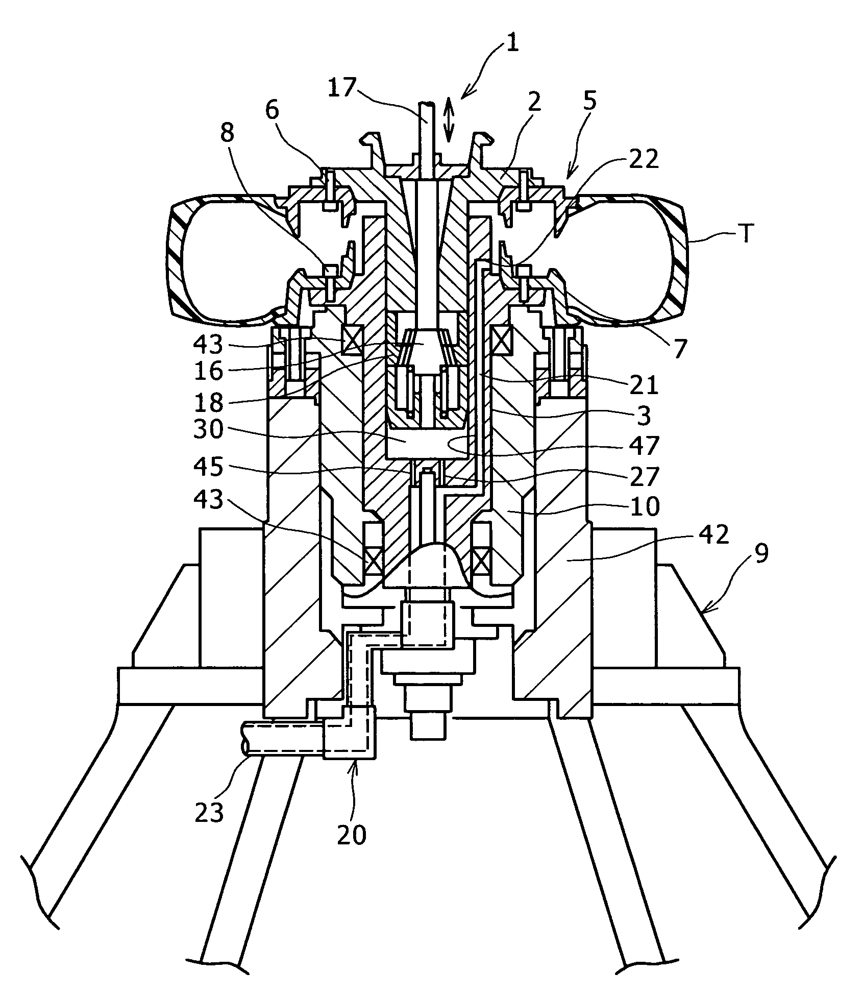
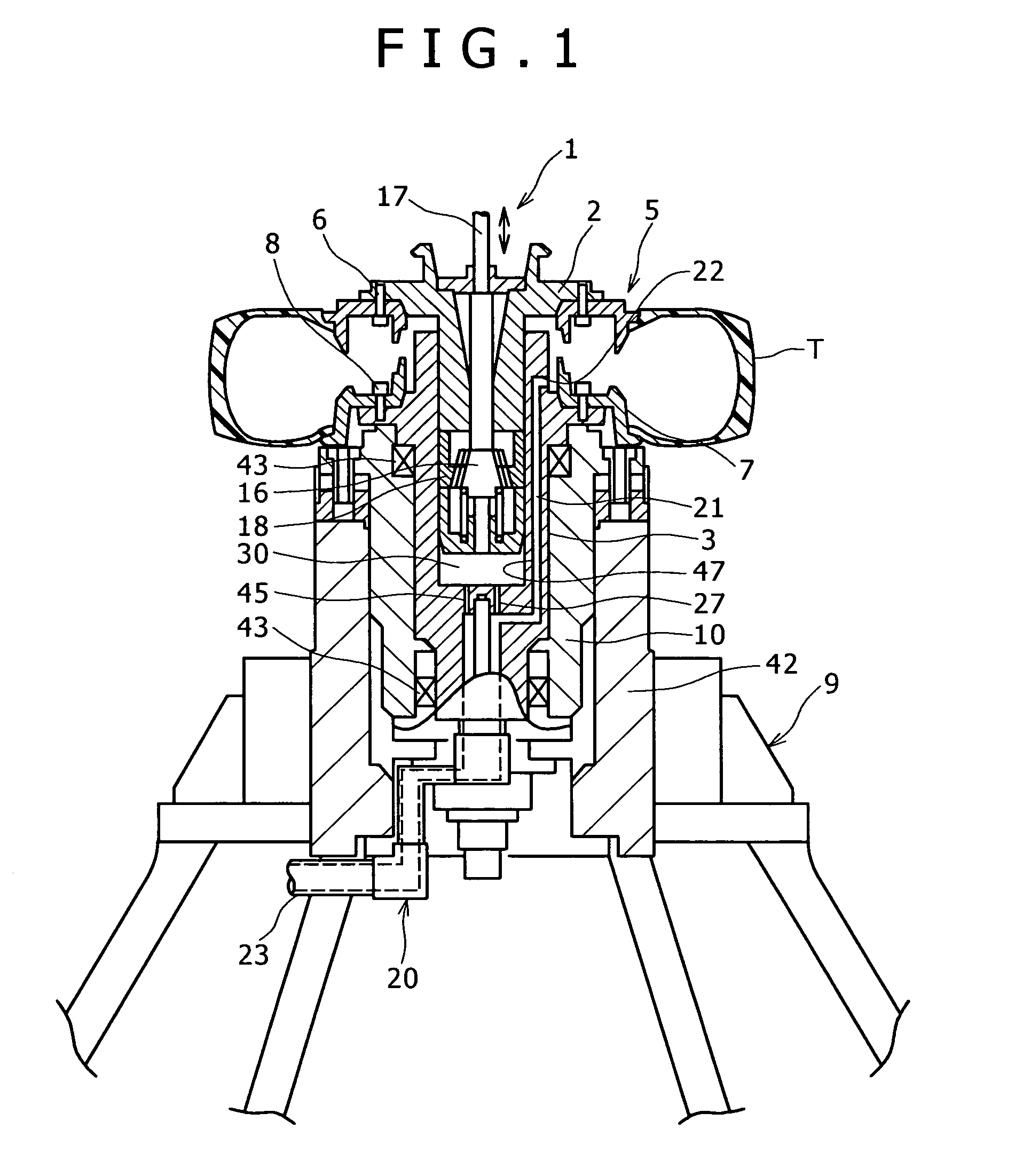
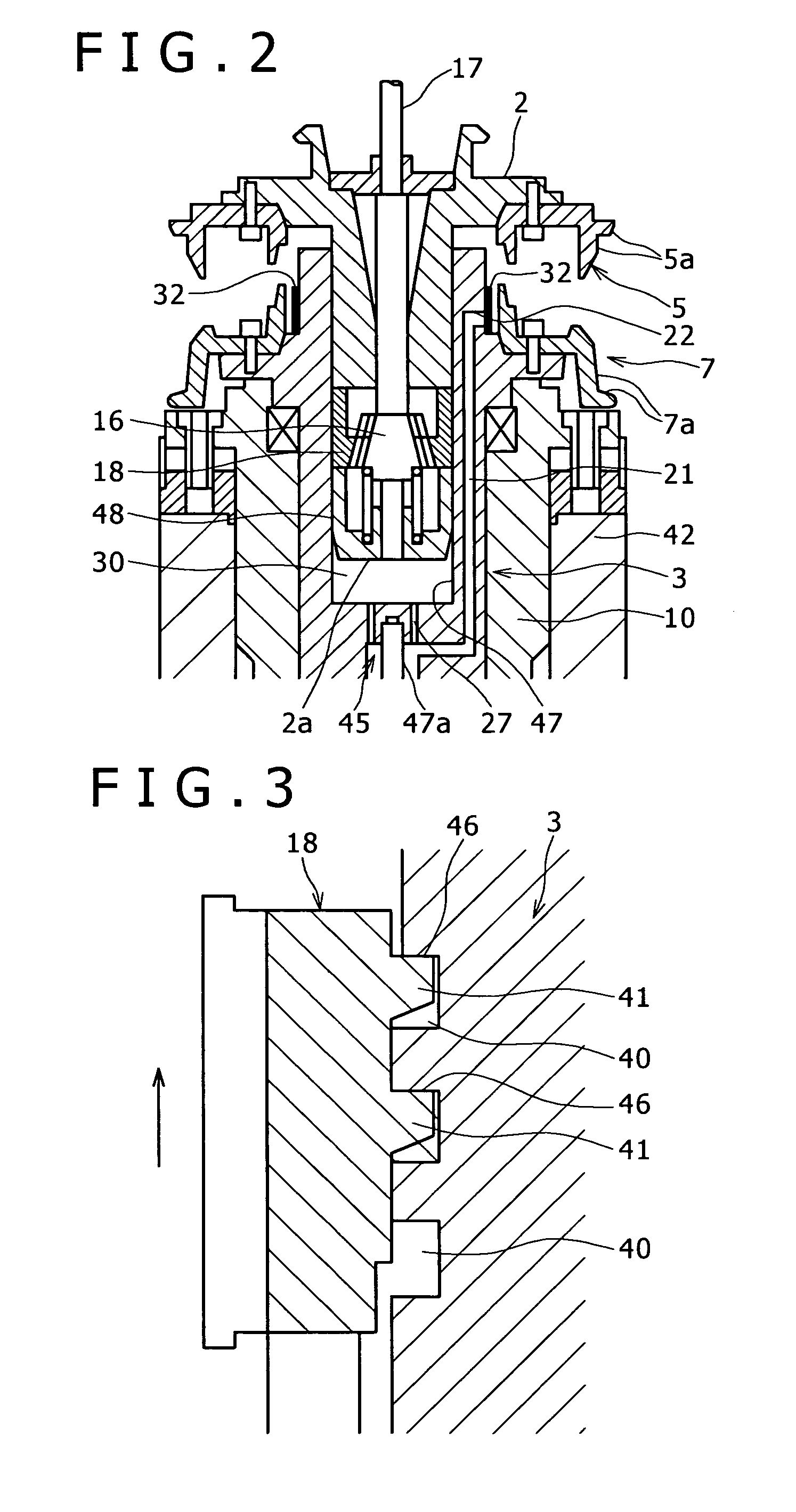
[0059]A description will now be given of a tire testing machine 1 according to the present invention with reference to FIGS. 1 to 4.
[0060]FIGS. 1 to 3 show the first embodiment of the tire testing machine 1 according to the present invention.
[0061]The tire testing machine 1 includes a tubular first spindle 3 whose one end opens largely, a second spindle 2 which has a columnar exterior, and is contained in the first spindle 3 thorough the opening, and a lock piece 18 which is engaged with the second spindle 2 so as to protrude from and retract into the second spindle 2 in the radial direction. The first spindle 3 and the second spindle 2 are vertically arranged, and relatively move, the first spindle 3 is designated as a lower spindle, and the second spindle 2 is designated as an upper spindle.
[0062]An upper rim 5 is fixed by means of bolts 6 to a bottom end portion of the upper spindle 2, and a lower rim 7 is fixed by means of bolts 8 to a top end portion of the lower spindle 3. Pos...
second embodiment
[0115]A description will now be given of a tire testing machine 50 according to the present invention with reference to FIGS. 5 to 15.
[0116]FIG. 5 shows an overall front view of the tire testing machine 50, and FIG. 6 shows an overall side view of the tire testing machine 50. FIG. 7 shows a detailed view of a spindle device provided for the tire testing machine 50.
[0117]It should be noted that the left / right direction of the page is the left / right direction, and the direction passing trough the page is the front / rear direction in FIG. 5, and the left / right direction of the page is the front / rear direction, and the direction passing trough the page is the left / right direction in FIG. 6.
[0118]As shown in FIGS. 5 to 7, the tire testing machine 50 includes a main frame 51 and a spindle device 52 which is supported by the main frame 51, and detachably mounts the tire T. Moreover, the tire testing machine 50 includes a drum device 53 which applies a rotation and a load on the tire T mount...
third embodiment
[0194]A description will now be given of a tire testing machine 110 according to the present invention with reference to FIGS. 16 to 20.
[0195]FIGS. 16 and 17 show an overall front view of the tire testing machine 110.
[0196]It should be noted that the left / right direction of the page is the left / right direction, and the direction passing trough the page is the front / rear direction in FIGS. 16 and 17.
[0197]The tire testing machine 110 includes a main frame 111 and a spindle device 112 which is supported by the main frame 111, and detachably mount the tire T.
[0198]Moreover, the tire testing machine 110 includes a drum device 113 which applies a rotation and a load on the tire T mounted on the spindle device 112.
[0199]The main frame 111 includes pillars 114 which are erected from an installation surface on front and rear, and left and right, connection bars 115 which connect top ends and bottom ends of the front and rear, and left and right pillars 114, and a mounting table 116 which mo...
PUM
 Abstract
Description
Claims
Application Information
 - R&D
- Intellectual Property
- Life Sciences
- Materials
- Tech Scout
- Unparalleled Data Quality
- Higher Quality Content
- 60% Fewer Hallucinations
Browse by: Latest US Patents, China's latest patents, Technical Efficacy Thesaurus, Application Domain, Technology Topic, Popular Technical Reports.
© 2025 PatSnap. All rights reserved.Legal|Privacy policy|Modern Slavery Act Transparency Statement|Sitemap|About US| Contact US: help@patsnap.com


