Oil filter remover

a technology of oil filter and remover, which is applied in the direction of filtration separation, liquid handling, separation processes, etc., can solve the problems of reducing engine efficiency and engine life, increasing the potential for wear, and reducing lubricity

Inactive Publication Date: 2008-03-11
WEINBERGER GRP THE
View PDF12 Cites 29 Cited by
  • Summary
  • Abstract
  • Description
  • Claims
  • Application Information

AI Technical Summary

Problems solved by technology

However, oil used in engines tends to break down with use over a period of time, such that the lubricity is reduced and the potential for wear increases.
Additionally, oil picks up particulate contaminates caused by engine wear that can score engine parts, also reducing engine efficiency and engine life.
However, there is often over 5 quarts of oil in an automobile, and more in most truck or larger engines, that needs to be removed when the oil and oil filter is changed.
This oil tends to leak from the engine as the oil filter is unscrewed from the engine, running down the oil filter onto the hands of the technician removing the oil filter, or onto the technician's clothes or face if positioned under the filter being removed.
In addition to dirtying the hands of the technician, the oil is generally changed when the oil is hot, so that the technician can be scalded by the hot oil.
However, this does not diminish the fact that the oil draining from the oil filter and engine where the oil filter is connected runs down the filer and gets on the hands of the technician when the oil filter is being removed.

Method used


Image

  • Oil filter remover
  • Oil filter remover
  • Oil filter remover

Examples


Embodiment Construction

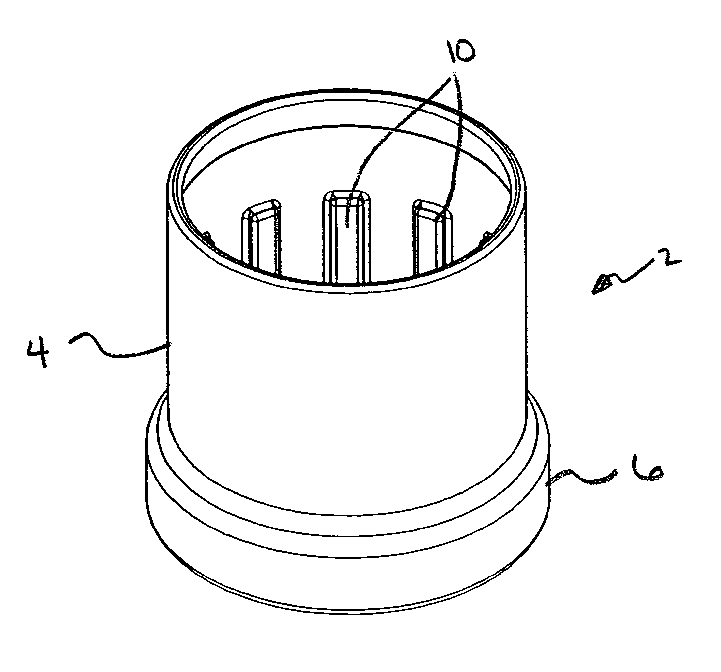
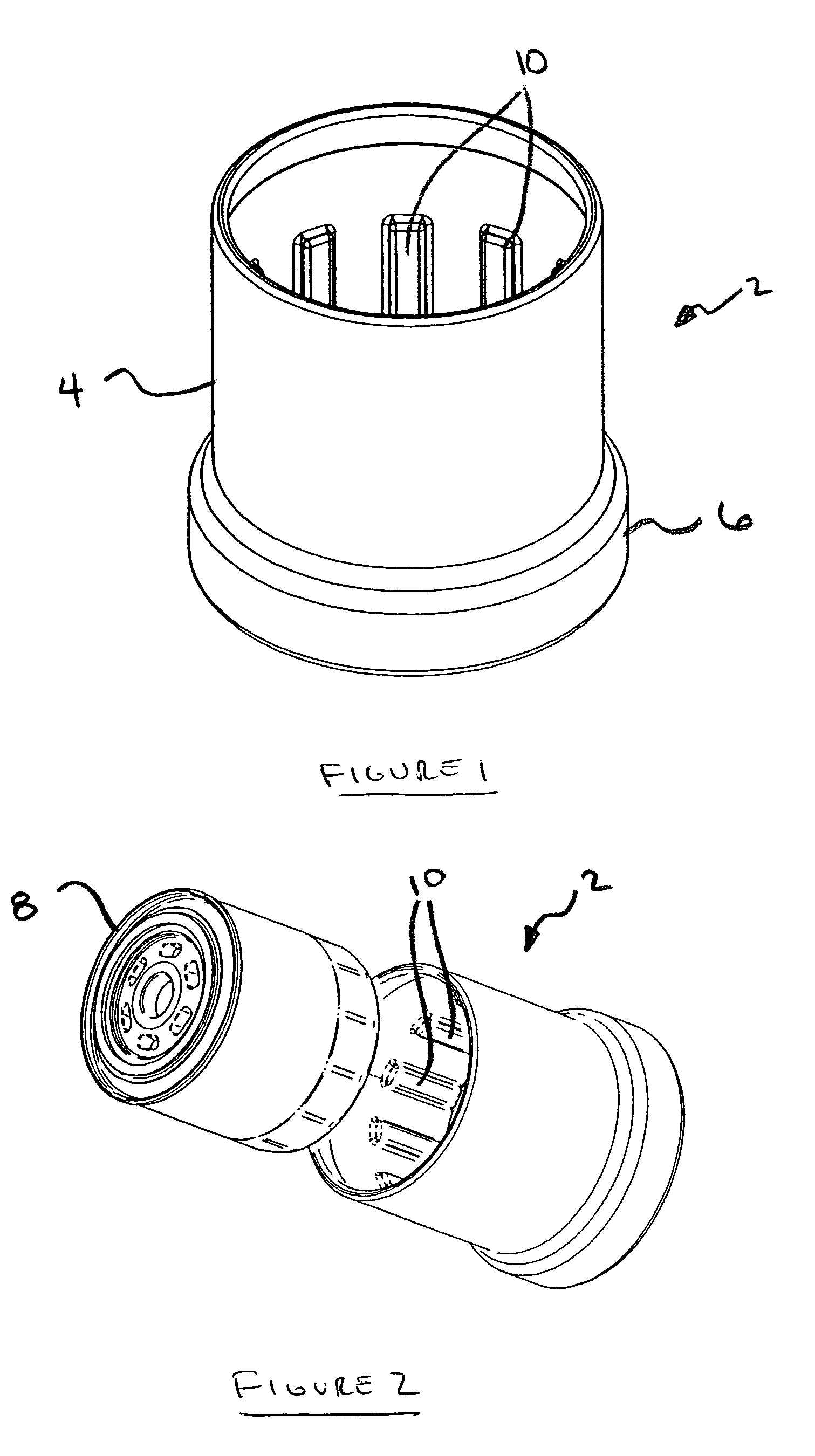
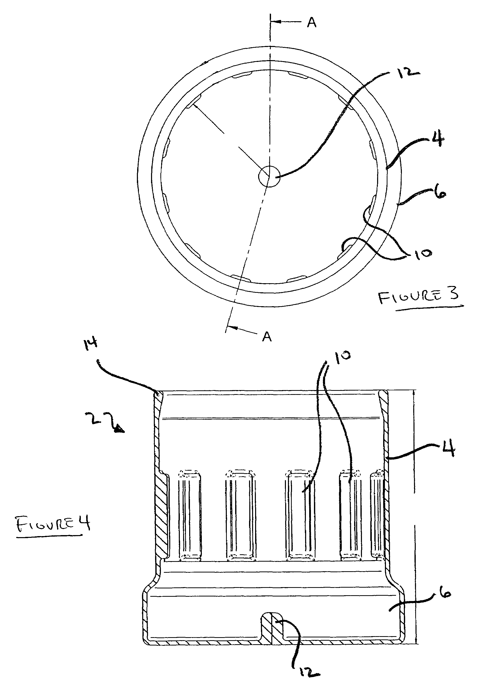
[0021]As shown in the drawings, and each of FIGS. 1-6, the present invention is directed to an oil filter remover 2, for removal of an oil filter 8, comprising a sleeve 4, having an open end and a closed end, and a reservoir 6. The interior of the sleeve 4 includes indentations 10 extending into the interior of the sleeve 4 to allow used oil to run between indentations 10 into the reservoir 6.

[0022]In the preferred embodiment, the closed sleeve 4 is preferably in a cylindrical configuration. Although other shapes may be used, including ovals or virtually any shapes with 3 or more sides, the circular configuration is preferred because it matches the circular configuration of most oil filter 8. In this regard, the opening of the sleeve 4 should be at least of sufficient size to accept the oil filter 8 to be removed.

[0023]The depth of the sleeve 4 is preferably enough so that the open end extends beyond the height of the oil filter 8. Of course, the sleeve 4 can be much deeper than the...


PUM


Abstract

An oil filter remover comprising a sleeve, having an interior surface, an exterior surface, an open end and a closed end with indentations on the interior surface, and a reservoir. The oil filter is slid into the oil filter remover and the oil filter is unscrewed, the excess oil being caught within the oil filter remover and collected within the reservoir.

Description

FIELD OF THE INVENTION[0001]The present invention relates generally to the field of mechanical tools for engine maintenance, and more particularly to tools for assisting in changing oil filters.BACKGROUND OF THE INVENTION[0002]Engines, as used in automobiles, trucks, boats, planes, power equipment and the like, require oil to lubricate moving parts. The oil is used to prevent excess wear, increase efficiency and increase engine life. However, oil used in engines tends to break down with use over a period of time, such that the lubricity is reduced and the potential for wear increases. Additionally, oil picks up particulate contaminates caused by engine wear that can score engine parts, also reducing engine efficiency and engine life. Therefore, the oil and oil filter must be changed regularly to keep an engine running properly.[0003]Since engine design commonly takes into account the fact that the oil and oil filter need to be changed regularly, the oil generally collects into an oi...

Claims


Application Information

Patent Timeline
Patent Type & Authority Patents(United States)
IPC IPC(8): B67B7/18B25B13/06
CPCB25B27/0042B01D2201/24
Inventor SAWYER, GEORGE MCLURE
Owner WEINBERGER GRP THE
Why Eureka
Try Eureka