Permanent magnet electric motor with reduced cogging torque

a permanent magnet, electric motor technology, applied in the direction of mechanical energy handling, magnetic circuit rotating parts, magnetic circuit shape/form/construction, etc., can solve the problems of reducing the cogging torque, and affecting the control performance of electric motors, so as to reduce the leakage flux and reduce the induced voltage constant ratio

Active Publication Date: 2008-03-11
MITSUBISHI ELECTRIC CORP
View PDF57 Cites 46 Cited by
  • Summary
  • Abstract
  • Description
  • Claims
  • Application Information

AI Technical Summary

Benefits of technology

[0007]The present invention has been achieved to solve the above-mentioned problems, and it is an object of the invention to provide a permanent magnet electric motor in which two frequency components of the cogging torque are removed and the rotor has a simple constitution.
[0010]This permanent magnet electric motor has an advantage that two frequency components of the cogging torque are decreased and the rotor has a simple construction, because the rotor and the stator are provided with the first and second stage skews.
[0012]This permanent magnet electric motor has an advantage that two frequency components of the cogging torque are lower than at the theoretical angle employed for the stage skew angle, and the rotor has a simple construction.
[0014]This permanent magnet electric motor has an advantage that the stator has a simple construction.
[0016]This permanent magnet electric motor has an advantage that the induced voltage constant ratio is not reduced by decreasing the leakage flux in the axial direction at the top end of the stator magnetic pole teeth owing to a clearance Lcg.

Problems solved by technology

The cogging torque generates a vibration or noise to cause the control performance of electric motor to be degraded.
However, if the theoretical angle of stage skew angle is actually applied to the permanent magnet electric motor, a reduced cogging torque is possibly less sufficient.
The leakage flux causing the cogging torque may occur at the stage portion of the permanent magnet and inside the rotor iron core, but the leakage flux inside the stator iron core is a main cause of the cogging torque.
Therefore, there was a problem that the cogging torque was not fully reduced because the theoretical angle was employed for the skew angle of the rotor.
Also, the constitution of the rotor was complex to remove two frequency components of the cogging torque.

Method used


Image

  • Permanent magnet electric motor with reduced cogging torque
  • Permanent magnet electric motor with reduced cogging torque
  • Permanent magnet electric motor with reduced cogging torque

Examples


embodiment 1

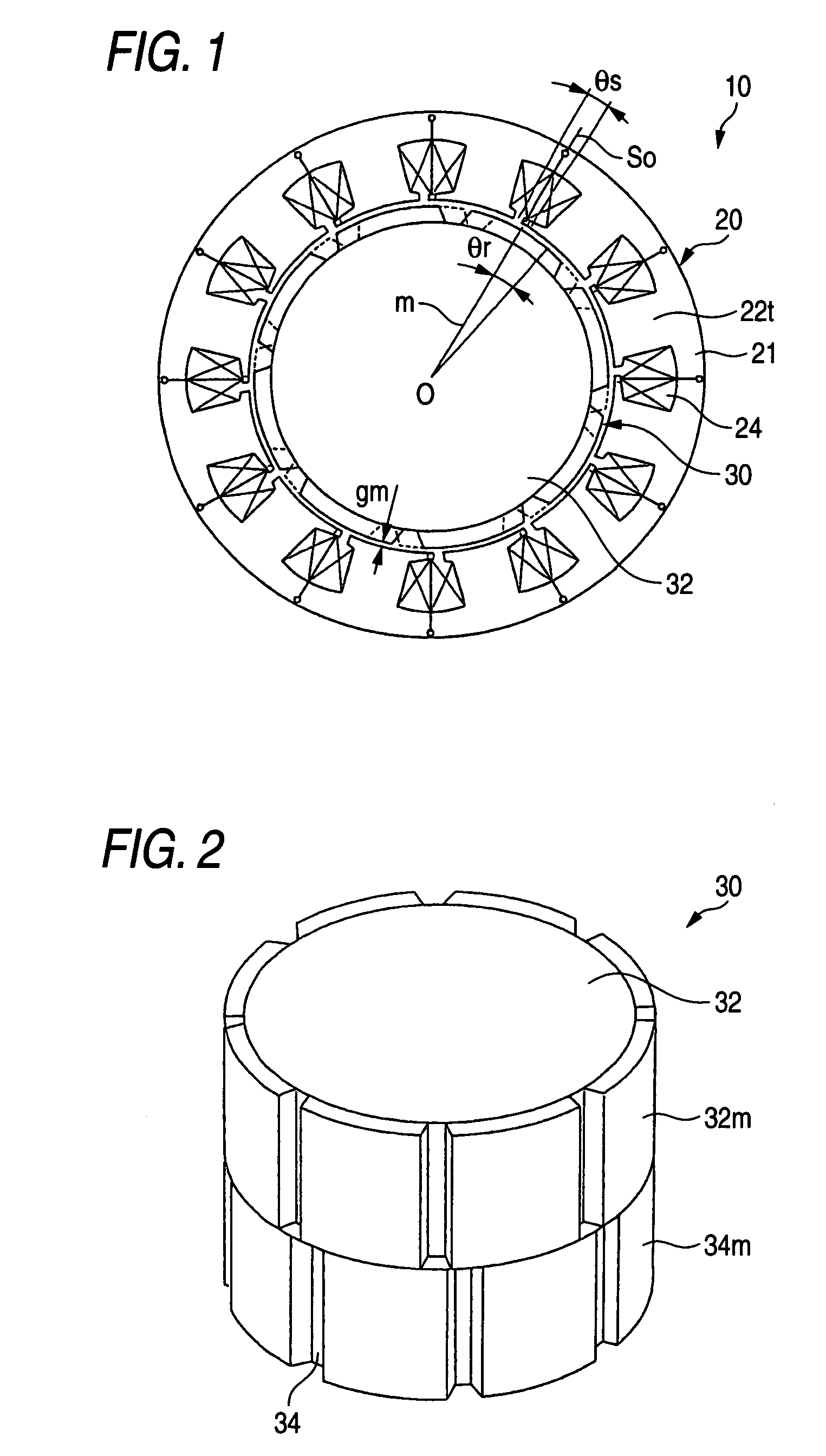
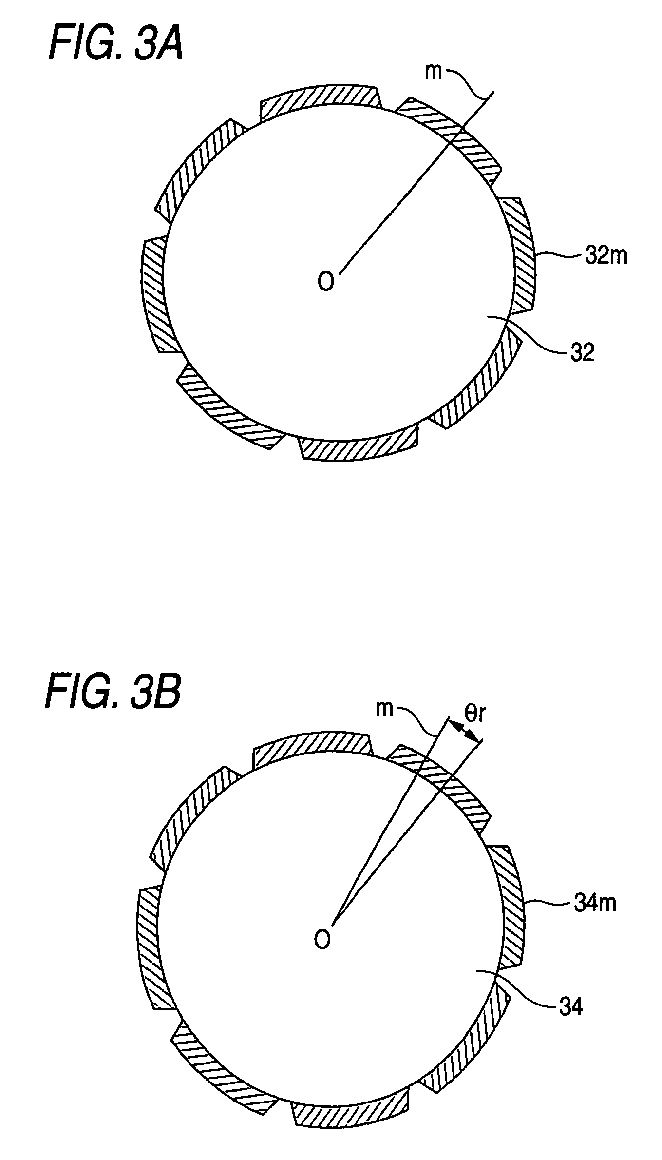
[0029]Referring to FIGS. 1 to 5, an embodiment 1 of the present invention will be described below. FIG. 1 is a side cross-sectional view of a permanent magnet electric motor according to the embodiment 1 of the invention. FIG. 2 is a perspective view of a rotor in the permanent magnet electric motor as shown in FIG. 1. FIGS. 3A and 3B are plan views of the rotor in the permanent magnet electric motor as shown in FIG. 1. FIG. 4 is a perspective view of a stator in the permanent magnet electric motor as shown in FIG. 1. FIGS. 5A-5C are plan views of an upper stage stator block, a middle stage stator block, and a lower stage stator block as shown in FIG. 4.

[0030]In FIGS. 1 to 5, the permanent magnet electric motor 10 is formed of an electromagnetic steel plate that is punched with the stator magnetic pole teeth 22t connected to a thin connecting portion, and comprises a stator iron core 21 of cylindrical shape, a stator 20 with 12 magnetic poles formed by winding a plurality of stator ...

embodiment 2

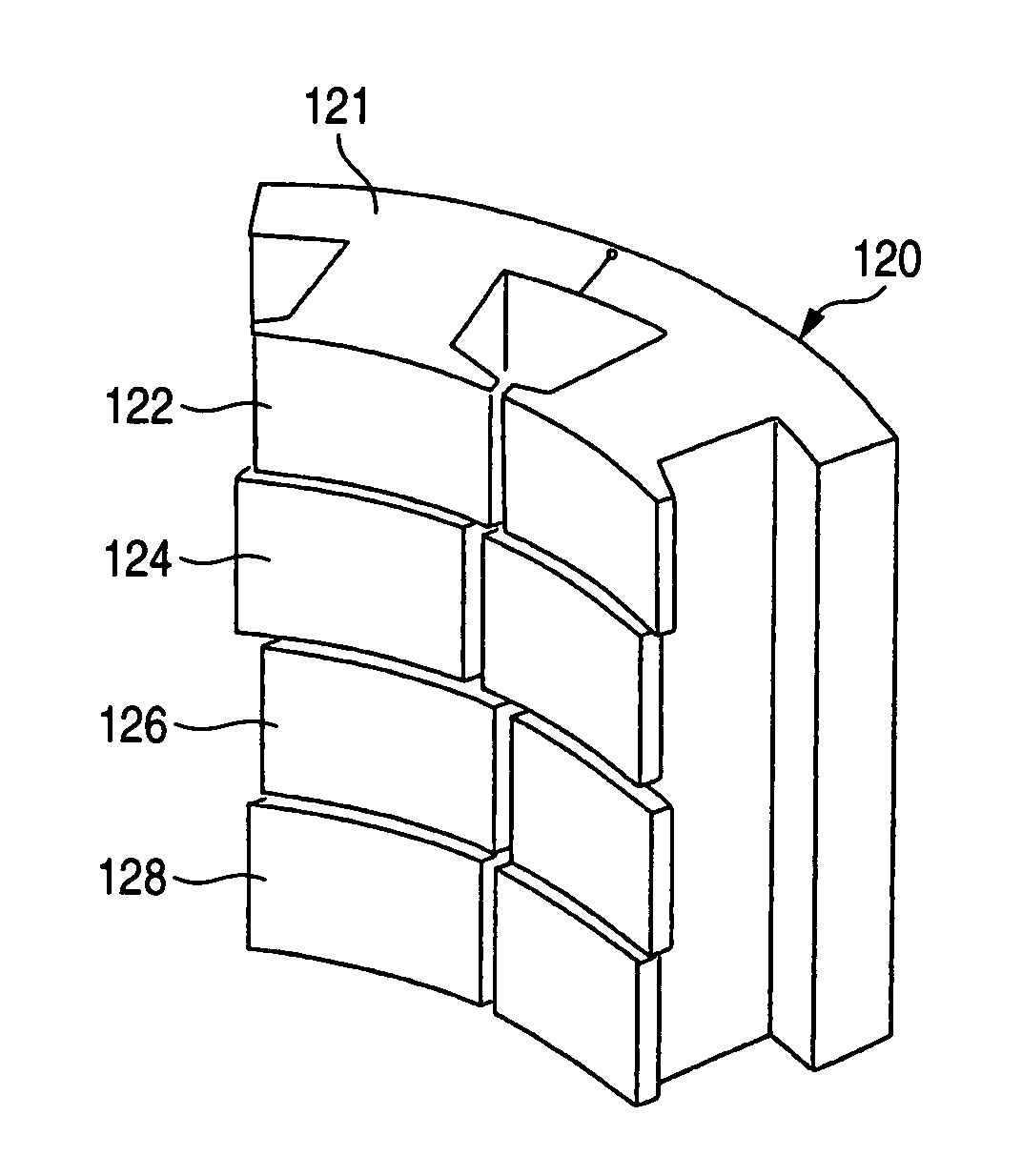
[0052]Another embodiment of the present invention will be described referring to FIG. 11. FIG. 11 is a perspective view of the stator according to another embodiment.

[0053]In the above embodiment 1, the fundamental wave component of cogging torque is reduced by providing the rotor iron cores 32 and 34 with the rotor skew angle θr, and the second order higher harmonic wave component of cogging torque is reduced by providing the stator iron cores 22, 24 and 26 with the stator skew angle θs.

[0054]In this embodiment, the rotor 30 is the same as in the embodiment 1, but the stator 120 is divided into four stator iron cores 122, 124, 126 and 128, whereby the second order higher harmonic wave component of cogging torque is reduced by providing the stator skew angle θs.

[0055]The stage skew angle between the stator iron core 122 and the top portion of stator magnetic pole teeth in the stator iron core 126 and between the stator iron core 124 and the top portion of the stator magnetic pole te...

embodiment 3

[0056]Referring to FIG. 12, another embodiment of the invention will be described below. FIG. 12 is a side cross-sectional view of a permanent magnet electric motor according to another embodiment of the invention.

[0057]In the above embodiments 1 and 2, the permanent magnet electric motor has the stator 20 disposed outside and the rotor 30 disposed inside the stator 20.

[0058]The permanent magnet electric motor 200 according to this embodiment has a rotor 230 disposed outside and a stator 220 disposed inside the rotor 230.

[0059]In the above embodiments 1 to 3, the rotor 30, 230 is formed with the skew angle θr for removing the fundamental wave component of cogging torque, and the stator 20, 220 is formed with the skew angle θs for removing the second order higher harmonic wave component of cogging torque. Conversely, the rotor 30, 230 may be formed with the skew angle θs for removing the second order higher harmonic wave component of cogging torque, and the stator 20, 220 may be form...


PUM


Abstract

A permanent magnet electric motor 10 comprises a rotor 30 provided with two stages of permanent magnets in the axial direction on an outer circumferential face of a rotor iron core, and having a shaft shifted by a stage skew angle θr in electrical angle to decrease a first frequency component of cogging torque in the circumferential direction of the rotor iron core between two stages of the permanent magnets, a stator iron core 21 of cylindrical shape provided with the stator winding for producing a rotating magnetic field causing the rotor 30 to be rotated, and a stator 20 dividing the stator iron core 21 into plural blocks in the axial direction, and shifted by a stage skew angle θs in electrical angle to decrease a second frequency component of the cogging torque in the circumferential direction of the stator iron core 21.

Description

TECHNICAL FIELD[0001]The present invention relates to improvements in a permanent magnet electric motor to reduce a cogging torque.BACKGROUND ART[0002]A permanent magnet electric motor produces a rotational variation called a cogging torque. The cogging torque generates a vibration or noise to cause the control performance of electric motor to be degraded. Therefore, a method for reducing the cogging torque was disclosed in JP-A-4-21330. According to this patent, to remove two frequency components of the cogging torque, permanent magnets are arranged at four stages in the axial direction of a rotor iron core and shifted in the circumferential direction of the rotor iron core to give rise to a skew effect, so that a plurality of permanent magnets are dislocated in the circumferential direction depending on an axial position of the rotor, namely, arranged on the surface of the rotor iron core at a skew angle (hereinafter referred to a stage skew angle).[0003]A theoretically calculated...

Claims


Application Information

Patent Timeline
Patent Type & Authority Patents(United States)
IPC IPC(8): H02K1/27H02K1/14H02K21/14H02K1/12H02K1/28H02K21/16H02K29/03
CPCH02K1/278H02K29/03H02K2201/06
Inventor MIYAZAKI, TAKASHIKIKUCHI, TOMOHIROKOMETANI, HARUYUKIYAMAGUCHI, SHINICHI
Owner MITSUBISHI ELECTRIC CORP
Why Eureka
Try Eureka