Quadrature LC voltage controlled oscillator with opposed bias and coupling control stages

a voltage control and oscillator technology, applied in oscillation generators, pulse automatic control, modulation, etc., can solve problems such as power dissipation and tail current reduction, and achieve the effect of efficient generation

Inactive Publication Date: 2008-03-11
AVAGO TECH WIRELESS IP SINGAPORE PTE
View PDF4 Cites 12 Cited by
  • Summary
  • Abstract
  • Description
  • Claims
  • Application Information

AI Technical Summary

Benefits of technology

[0016]It is an aspect of the invention to provide a cross coupled VCO oscillator pair wherein the coupling coefficients on cross coupled paths between two complementary PMOS / NMOS switches are controlled and switched synchronously with oscillation. The oscillators produce periodic outputs at a controllable frequency, in quadrature phase relationship. According to an inventive aspect, VCO tail current levels and coupler circuit tail current levels are balanced against one another by sharing a current mirror control wherein two sides share a current supply in a manner that when one of the coupler circuit and an associated VCO is driven to increase its tail current level, the other of the coupler circuit and VCO is driven to decrease its tail current. The two are driven in a coordinated manner in opposite directions. In this way, the sum of the tail currents of the coupler circuit and VCO are controlled over the range of frequency control, instead of providing points in the control ranges wherein the total current dissipation is distinctly higher that at other points, due to driving the coupler circuit particularly hard.
[0018]The invention permits efficient generation of quadrature oscillation signals over a control range while limiting the total biasing current of the oscillator pair and its associated coupling elements.

Problems solved by technology

A tuning variation leading to increased tail current and power dissipation in one type, causes decreased tail current and power dissipation in the other, and vice versa.

Method used


Image

  • Quadrature LC voltage controlled oscillator with opposed bias and coupling control stages
  • Quadrature LC voltage controlled oscillator with opposed bias and coupling control stages
  • Quadrature LC voltage controlled oscillator with opposed bias and coupling control stages

Examples


Embodiment Construction

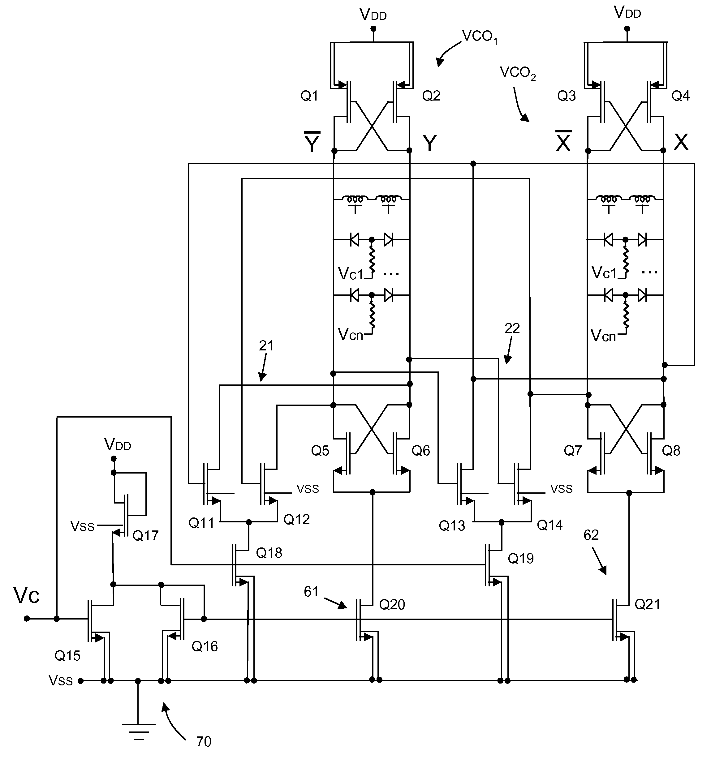
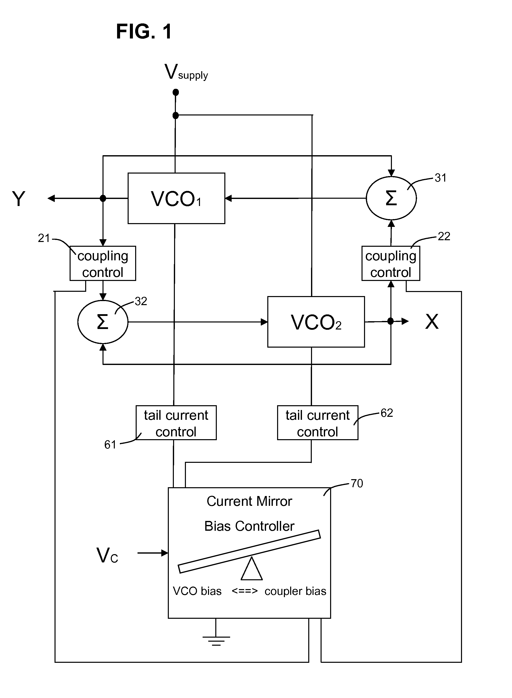
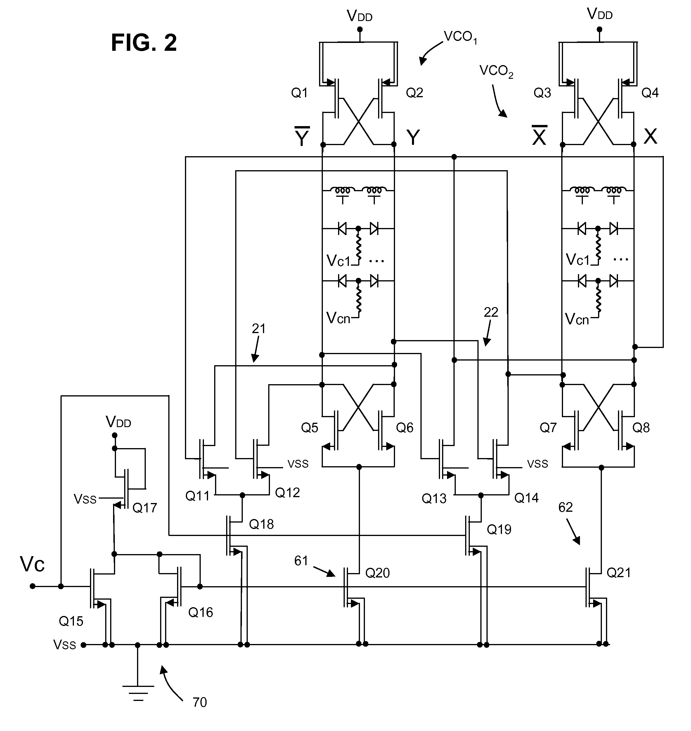
[0024]FIG. 1 is a block diagram that illustrates the structure and function of the invention. FIG. 2 is a schematic diagram illustrating a practical embodiment.

[0025]A pair of voltage controlled oscillators VCO1 and VCO2 are connected to one another including through couplers 21, 22, so as to operate as described in the background section above, producing two quadrature outputs X and Y, namely periodic signals that are synchronous but 90 degrees out of phase. The frequency of the outputs is controlled by a control voltage input Vc, the same voltage input level defining the maximum coupling proportion at both couplers 21, 22 associated with summing nodes 31, 32.

[0026]As shown in FIG. 2, each of the two VCOs can comprise a cross-coupled differential pair amplifier and an LC resonant tank. The transistor members of the cross-coupled pairs, for example Q1 and Q2, and Q5 and Q6 (for VCO1) behave like an amplifier and provide negative resistance sufficient to compensate for the LC tank pa...


PUM


Abstract

A voltage controlled oscillator unit is provided with cross coupled voltage controlled oscillators to generate quadrature phases. One control stage adjusts coupling between the oscillators. Another control stage adjusts the tail current that applies operating bias to the oscillators and to the couplers, respectively. The cross coupling and tail current control stages are arranged so that tuning one simultaneously and oppositely tunes the other for simultaneous adjustment in opposite directions. This limits the power consumption of the oscillator unit throughout the range of frequency control.

Description

FIELD OF THE INVENTION[0001]The invention concerns a solid state voltage-controlled oscillator arrangement with two oscillator stages coupled by switching elements so as to generate quadrature phase outputs. In addition to switching elements that operate alternately to couple and decouple the oscillator stages, additional switching elements are provided alternately to apply or to decouple operational bias that produces tail current. The stage-coupling and tail current switching elements operate in phase with one another but in opposite directions. The result is reduced overall power consumption.BACKGROUND[0002]It is known to couple together two substantially identical resonant LC voltage controlled oscillators (VCO) as a unit that produces quadrature outputs. The oscillation frequency of the unit can be tuned by adjusting the coupling coefficients between the two oscillators.[0003]FIG. 3, labeled “prior art,” is a block diagram schematic showing two coupled LC oscillators. Each has ...

Claims


Application Information

Patent Timeline
Patent Type & Authority Patents(United States)
IPC IPC(8): H03B5/12H03B27/00H03L7/24
CPCH03B27/00H03L7/00H03L7/099
Inventor CHEN, JINGHONG
Owner AVAGO TECH WIRELESS IP SINGAPORE PTE
Why Eureka
Try Eureka