Multiple cavity low-emissivity coatings

a technology of low-emissivity coatings and multi-cavity, applied in the field of thin film coatings, can solve the problems of reducing the visible transmission of the coating, negatively affecting the color of the coating, and reducing the durability of the coating

Active Publication Date: 2008-03-11
CARDINAL CG
View PDF124 Cites 60 Cited by
  • Summary
  • Abstract
  • Description
  • Claims
  • Application Information

AI Technical Summary

Problems solved by technology

However, this can also reduce the visible transmission of the coating, and / or negatively impact the color of the coating, and / or decrease the durability of the coating.
Perhaps for these reasons, low-emissivity coatings with three silver layers have not found much place in the market.

Method used


Image

  • Multiple cavity low-emissivity coatings
  • Multiple cavity low-emissivity coatings
  • Multiple cavity low-emissivity coatings

Examples


Embodiment Construction

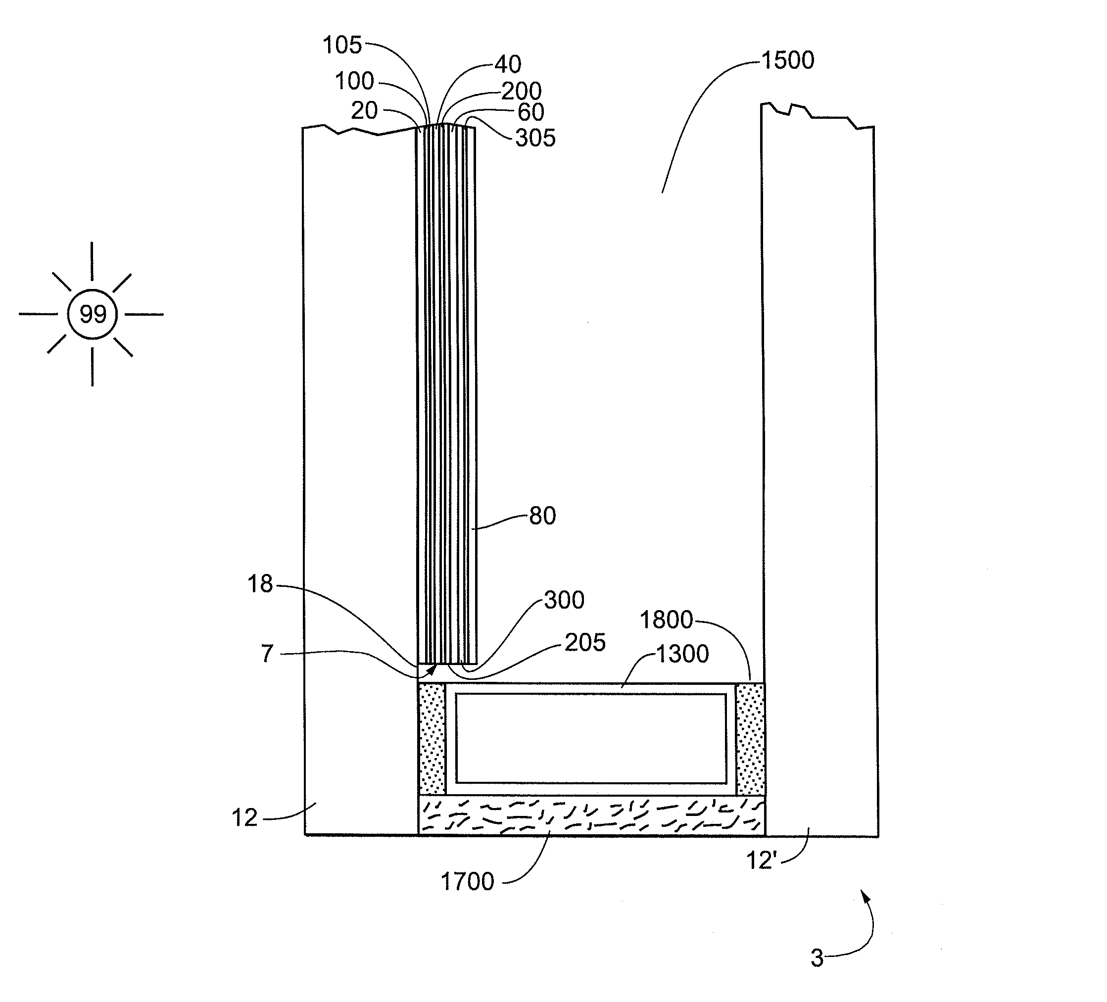
[0016]The following detailed description is to be read with reference to the drawings, in which like elements in different drawings have like reference numerals. The drawings, which are not necessarily to scale, depict selected embodiments and are not intended to limit the scope of the invention. Skilled artisans will recognize that the examples provided herein have many useful alternatives that fall within the scope of the invention.

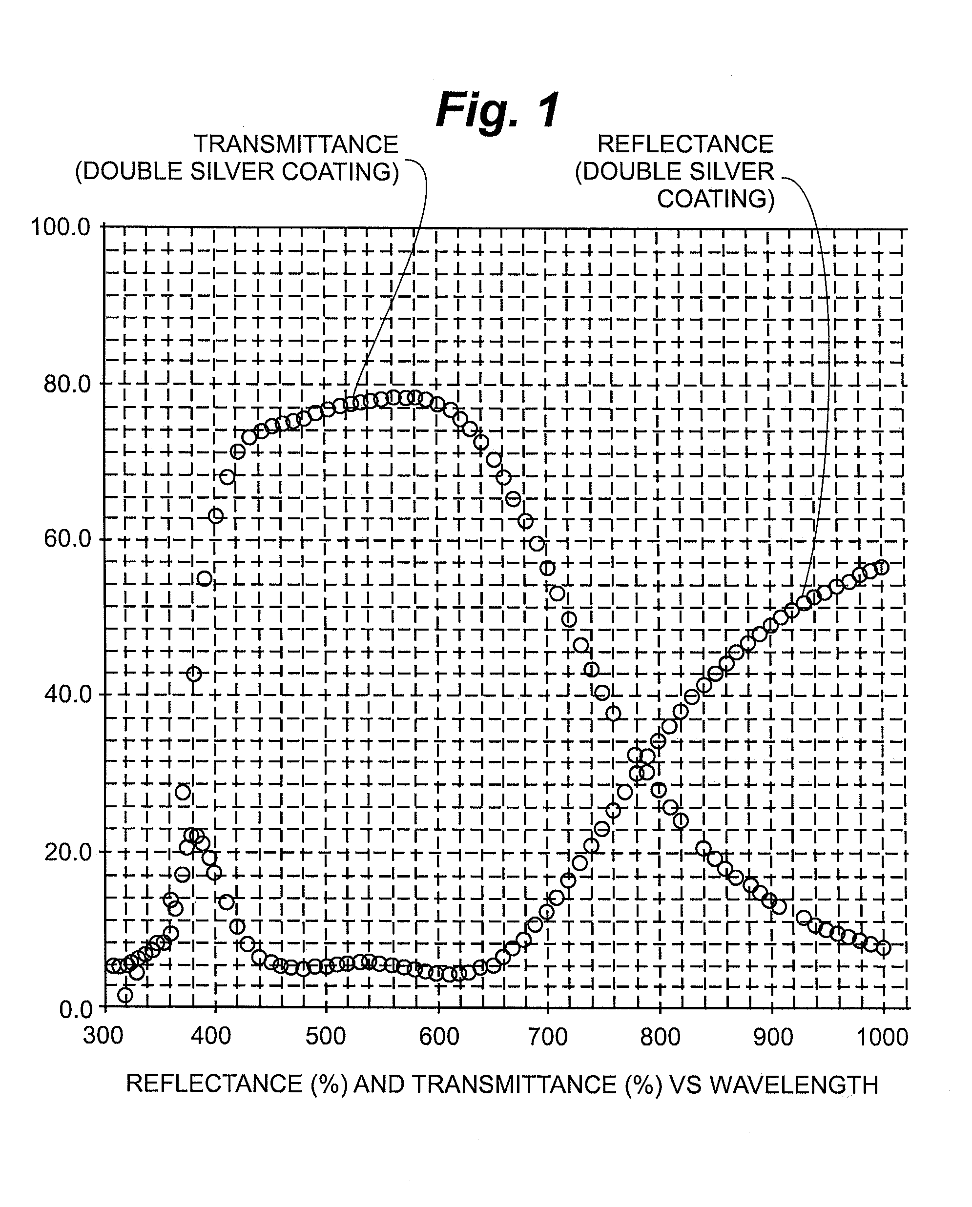
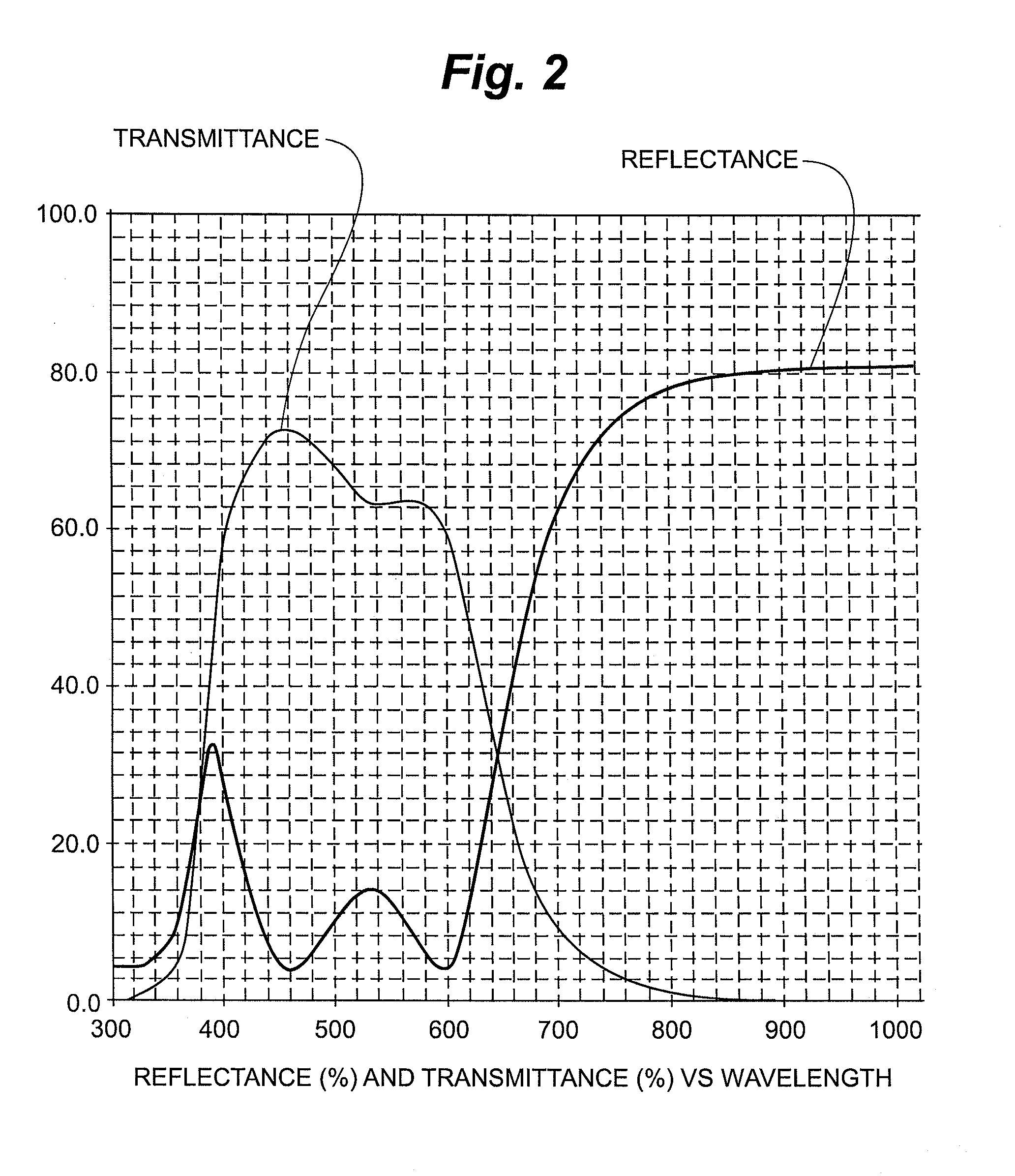
[0017]Single and double silver low-emissivity coatings have been known in the art for years. Single silver low-emissivity coatings provide advantageous infrared reflection, commonly in the neighborhood of 97%. Double silver low-emissivity coatings offer further improvements in terms of high visible transmission and high infrared reflection. There are, however, practical ceilings on the infrared reflection levels that can be achieved using a double silver low-emissivity coating. For example, while increasing the amount of silver in a double silver coatin...


PUM

PropertyMeasurementUnit
thicknessaaaaaaaaaa
solar heat gain coefficientaaaaaaaaaa

Abstract

Multiple cavity low-emissivity coatings. The coating includes three infrared-reflection film regions, which may each include silver.

Description

RELATED APPLICATIONS[0001]The present application claims priority to U.S. utility application Ser. No. 11 / 360,266, filed on Feb. 23, 2006 (“the '266 application”), and to U.S. provisional application No. 60 / 725,891, filed on Oct. 11, 2005, the entire contents of each which are incorporated herein by reference. The present application is a continuation-in-part of the '266 application.FIELD OF THE INVENTION[0002]The present invention relates to thin film coatings for glass and other substrates. In particular, this invention relates to low-emissivity coatings that are reflective of infrared radiation. Also provided are methods and equipment for depositing thin film coatings.BACKGROUND OF THE INVENTION[0003]Low-emissivity coatings are well known in the art. Typically, they include one or two layers of infrared-reflection film and two or more layers of transparent dielectric film. The infrared-reflection film, which generally is a conductive metal like silver, gold, or copper, reduces th...

Claims


Application Information

Patent Timeline
Patent Type & Authority Patents(United States)
IPC IPC(8): F21V9/04
CPCC03C17/36C03C17/3626C03C17/3639C03C17/3644C03C17/3652C03C17/366C03C17/3681C23C14/568E06B3/6715C03C17/3613Y10T428/24942C03C2217/78C03C2218/153C03C2218/154Y10T428/24612Y10T428/2495Y10T428/24975Y10T428/31504C03C17/3642C03C2217/211C03C2217/216C03C2218/156C23C14/086C23C14/185C23C14/35E06B9/24E06B2009/2417G02B5/208G02B5/26Y02B80/22
Inventor HARTIG, KLAUS
Owner CARDINAL CG
Why Eureka
Try Eureka