
Thin film coating having transparent base layer

a technology of thin film and base layer, applied in the field of thin film coating, can solve the problems of high tempering temperature, complicated procedure, and high cost, and achieve the effect of reducing the problem of corroded substrates and reducing the formation of haz

Inactive Publication Date: 2005-07-19
CARDINAL CG
View PDF118 Cites 63 Cited by
  • Summary
  • Abstract
  • Description
  • Claims
  • Application Information

AI Technical Summary

Benefits of technology

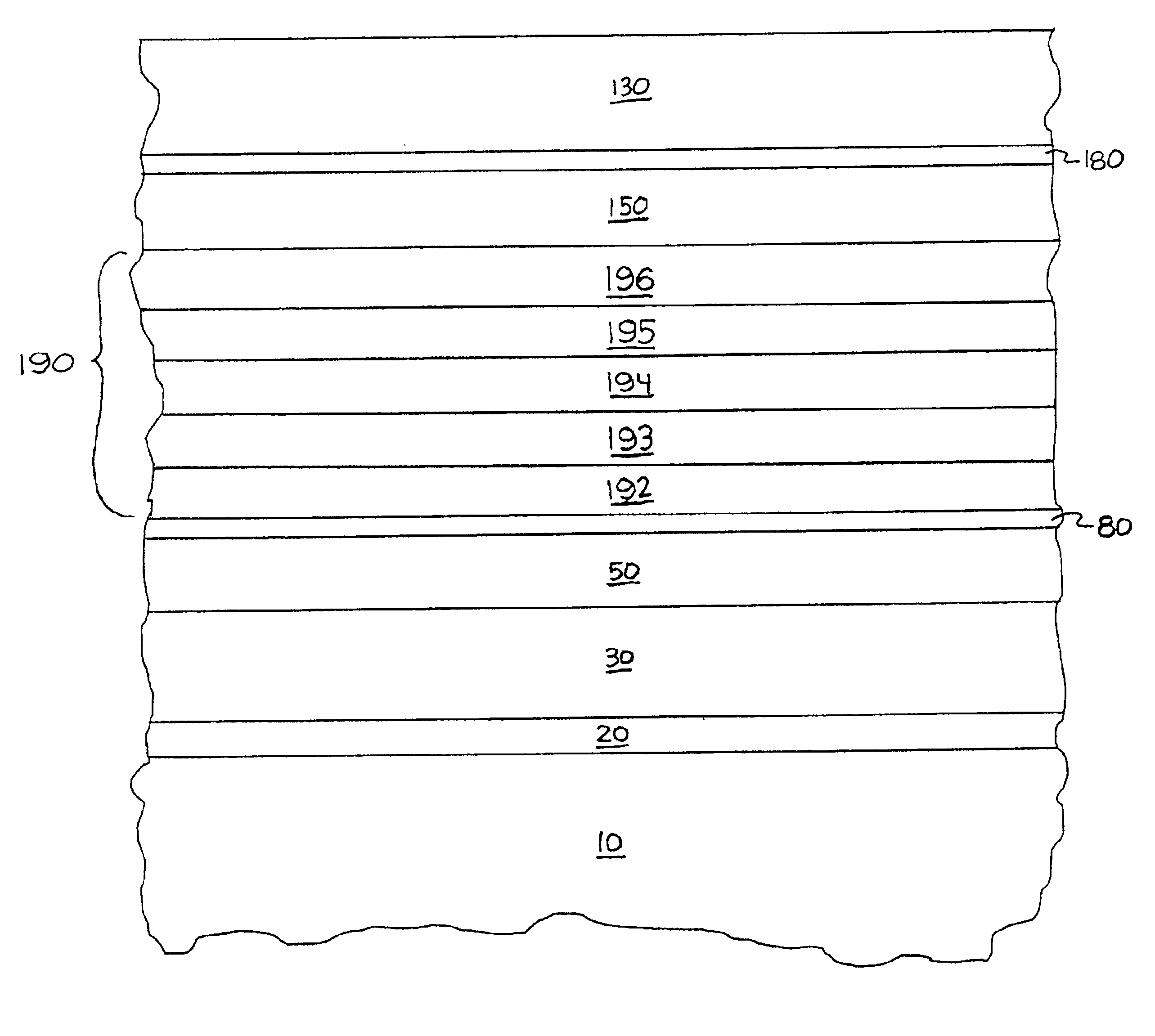
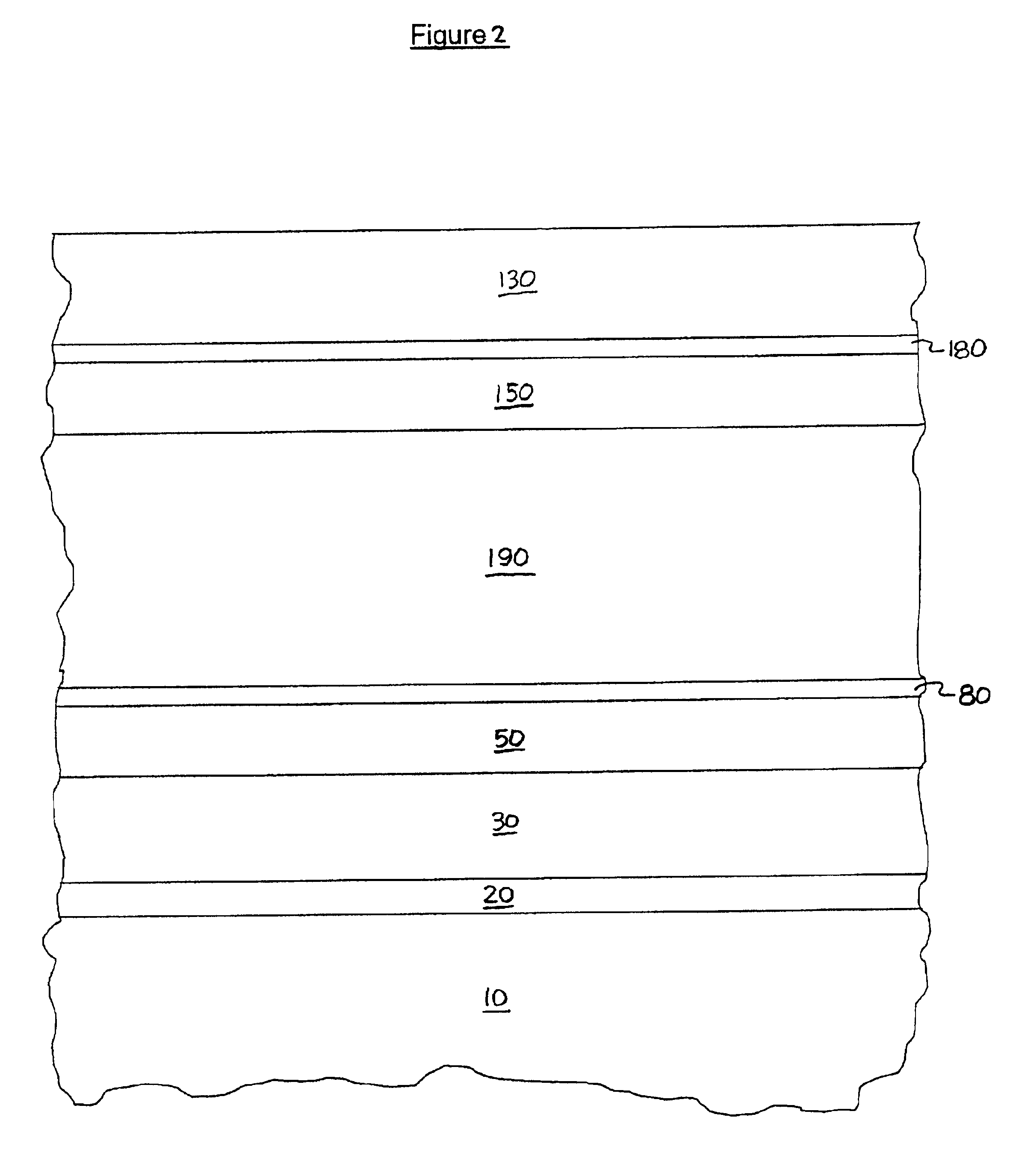
[0017]It has now been discovered that thin film coatings can be provided with certain base layers to reduce problems associated with corroded substrates. For example, a silicon dioxide base layer has been found to significantly reduce the formation of haze that has otherwise been observed when moisture corroded glass is coated with a temperable low-emissivity coating. Benefits of the present base layer are believed to extend to virtually any thin film coating that may be deposited upon a corroded substrate (e.g., moisture corroded glass).

Problems solved by technology

Many low-emissivity film stacks that employ silver as the infrared-reflective material (i.e., silver-based low-emissivity coatings) cannot withstand elevated tempering temperatures without some deterioration of the silver.
However, this procedure tends to be complicated and costly and, more problematically, may produce non-uniform coatings.
While these protective layers prevent oxygen and nitrogen from reaching the silver films, they become largely oxidized and / or nitrided themselves.
Insofar as the oxides and nitrides of the protective metals are more transparent than the protective metals themselves, this typically causes an increase in the transmissivity of the coating.
When these protective layers are too thin, they tend not to fully protect the infrared-reflective material during heat treatment.
For example, when silver in a low-emissivity coating is not aptly protected, tempering appears to cause the silver to become non-continuous, forming islands of silver breaking up the originally continuous layer.
For example, substrate defects may first appear, or may become more visible, after heat treatment.
As is well known in the art, glass is vulnerable to becoming corroded when exposed to moisture (e.g., water in the air of ambient glass processing and storage environments).
In fact, it is virtually impossible for a manufacturer of coated glass to assure that the raw glass it uses (i.e., coats) is completely free of moisture corrosion.
Surface defects may also result when uncoated glass sheets are engaged by glass handling equipment.
Thus, the manufacture of high quality coated glass can be challenging due to the commonly less than optimal quality of raw (i.e., uncoated) glass.
Not only may this yield coated glass with an undesirably rough coated surface, it can also have adverse effects on the desired properties of the coating.
For example, temperable low-emissivity glass has been found to exhibit an objectionable appearance more frequently when produced with glass that is old (and more likely corroded by exposure to moisture) than when produced with fresh glass.
Similarly, temperable low-emissivity glass has been found to exhibit an objectionable appearance more frequently when produced with glass that has been stored under conditions promoting moisture corrosion (e.g., high humidity).
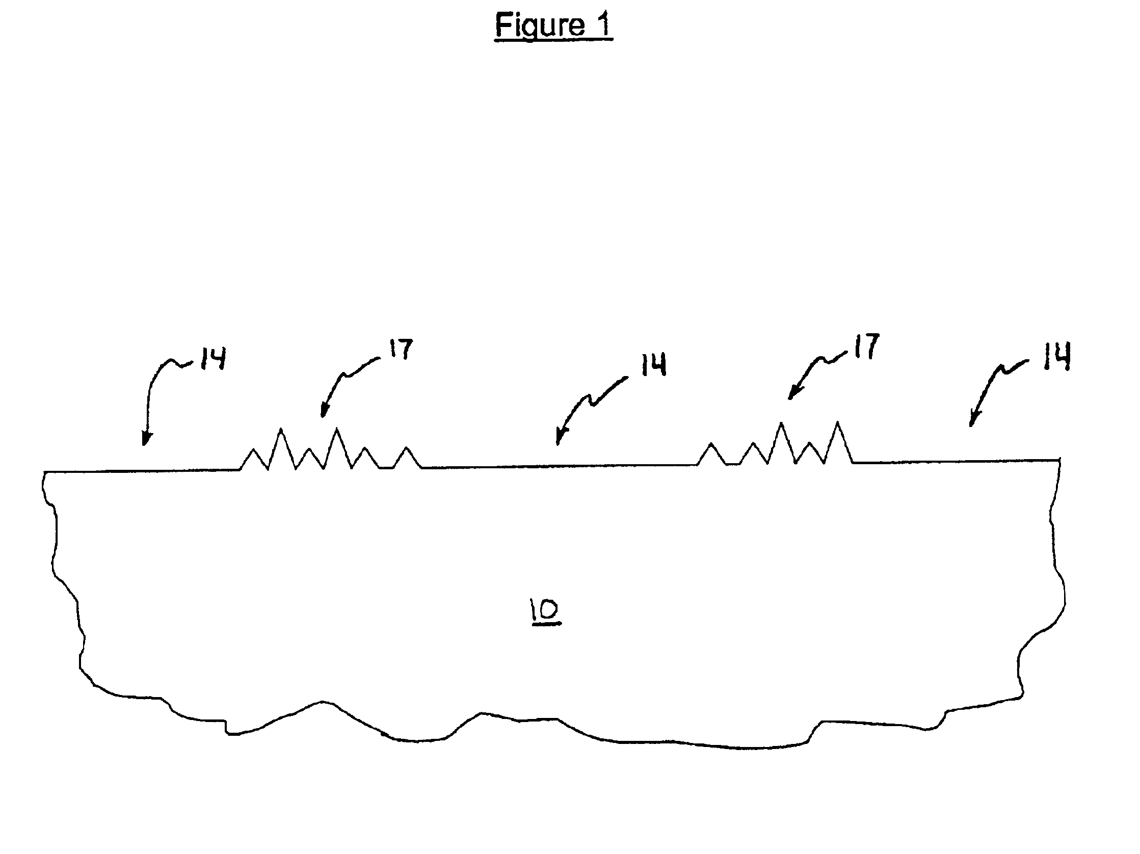
Such glass tends to have a non-uniform appearance, characterized by local areas of haze and low transparency.
However, this may not improve the appearance of the coated glass.
Further, the transparency of the coating may be decreased, and the color of the coated glass may be adversely affected.
Surprisingly, no matter what thickness is selected for the protective layers, there tend always to be local areas of haze (e.g., white haze, red haze, or both) and low transparency, which give the glass a non-uniform appearance.

Method used


Image

  • Thin film coating having transparent base layer
  • Thin film coating having transparent base layer
  • Thin film coating having transparent base layer

Examples


example 1

[0092]Sheets of conventional soda lime glass (having a thickness of 3 mm) were obtained. Two batches of the glass sheets were coated with double-silver low-emissivity coatings. The coating on the first batch of glass sheets was provided with a silicon dioxide base layer in accordance with the present teaching. The first batch of coated glass is referred to herein as Sample A. The coating on the second batch of glass sheets was equivalent to the Sample A coating, except that the silicon dioxide base layer was omitted. The second batch of coated glass is referred to herein as Sample B. All of the Sample A and Sample B films were deposited by magnetron sputtering.

[0093]Sample A

[0094]As noted above, the coating applied to the first batch of sheets was provided with a silicon dioxide base layer. The base layer had a thickness of about 80 angstroms and was applied directly upon one of the major surfaces of the substrate. Directly upon the silicon dioxide base layer was applied a layer of ...


PUM

PropertyMeasurementUnit
thicknessaaaaaaaaaa
thicknessaaaaaaaaaa
thicknessaaaaaaaaaa

Abstract

The invention provides thin film coatings that have a transparent base layer. For example, the invention provides low-emissivity coatings with a transparent base layer. In certain embodiments, a silicon dioxide base layer is used. Methods of producing thin film coatings having a transparent base layer are provided as well. In one embodiment, sputter deposition is utilized to produce these coatings.

Description

FIELD OF THE INVENTION[0001]The present invention provides thin film coatings for glass and other substrates. More particularly, this invention provides thin film coatings that are particularly durable to heat treatment (e.g., tempering). The invention also provides methods for producing coatings of this nature, as well as substrates bearing these coatings.BACKGROUND OF THE INVENTION[0002]Low-emissivity coatings are well known in the art. Typically, they include one or more layers of infrared-reflective material and two or more transparent dielectric layers. The infrared-reflective layers, which are typically conductive metals such as silver, gold, or copper, reduce the transmission of radiant heat through the coating. The transparent dielectric layers are used primarily to reduce visible reflectance and to control other properties of the coatings, such as color. Commonly used transparent dielectrics include oxides of zinc, tin, and titanium. Low-emissivity coatings are commonly dep...

Claims


Application Information

Patent Timeline
Patent Type & Authority Patents(United States)
IPC IPC(8): C03C17/36C23C14/18B32B7/02
CPCC03C17/36C03C17/3618C03C17/3626C03C17/3639C03C17/3644C03C17/3652C23C14/185C03C17/366Y10T428/12611C03C2217/734C03C2217/78Y10T428/12576Y10T428/12618Y10T428/31612
Inventor HARTIG, KLAUSKRISKO, ANNETTE J.
Owner CARDINAL CG
Learn More