Shock-absorbing member, shock-absorbing method of electronic device employing the member, and electronic device adapting the member and the method

a technology of electronic devices and shock absorption, applied in the field of shock absorption members, can solve the problems of increasing the portable use increasing the shock given to the device, and increasing the chance of such portable electronic equipment to receive great shocks, so as to achieve the effect of large shock absorption capability and increased reliability of the devi

Active Publication Date: 2008-03-11
PANASONIC CORP
View PDF24 Cites 15 Cited by
  • Summary
  • Abstract
  • Description
  • Claims
  • Application Information

AI Technical Summary

Benefits of technology

[0016]Because the electronic device of the present invention is manufactured in accordance with above-mentioned shock-absorbing method incorporating the constitutions, the device is provided with substantially a large shock-absorbing capability even for a severe shock which may be caused by such as dropping of the device in portable use, therewith the main body of the electronic equipment is prevented from receiving a large shock avoiding a serious damage, and reliability of the device is increased high.

Problems solved by technology

With this trend, chances for such portable electronic equipment to receive great shocks caused by dropping during its portable usage are also increasing.
With further advancement of reduction in size and weight of devices, dropping height of a device during carriage tends to become high, accordingly the shock given to the device is becoming still greater.
There also is another problem left that increasing the thickness of shock-absorbing member 62 makes the size of electronic device 72 larger, making it hard for the device to realize further miniaturization.
Namely, even if the thickness of the shock-absorbing member is increased against a large dropping impact amounting to 10,000 G or above, although the shock-absorbing capability becomes high at the initial stage of receiving the impact, the shock-absorbing member is rapidly deformed, and loses its resiliency restoring capability therefore a shock-absorbing capability of the member is lowered, as a result, the device is subjected to receiving a great shock in a relatively short period of time.
Thus, it has been difficult for them to cope with a very large impact.
However, if substantially a large dropping impact reaching 10,000 G or above is applied, even if the hard second-shock-absorbing-member is used, as long as it is used for absorbing the shock only with its elasticity deforming resistivity, it has to be assumed that it will be difficult for the united member to alleviate the impact force effectively and avoid a fatal damage to electronic device main body 61.

Method used


Image

  • Shock-absorbing member, shock-absorbing method of electronic device employing the member, and electronic device adapting the member and the method
  • Shock-absorbing member, shock-absorbing method of electronic device employing the member, and electronic device adapting the member and the method
  • Shock-absorbing member, shock-absorbing method of electronic device employing the member, and electronic device adapting the member and the method

Examples


Embodiment Construction

[0032]An exemplary embodiment of the present invention is described hereinafter using the drawings.

PREFERRED EMBODIMENT OF INVENTION

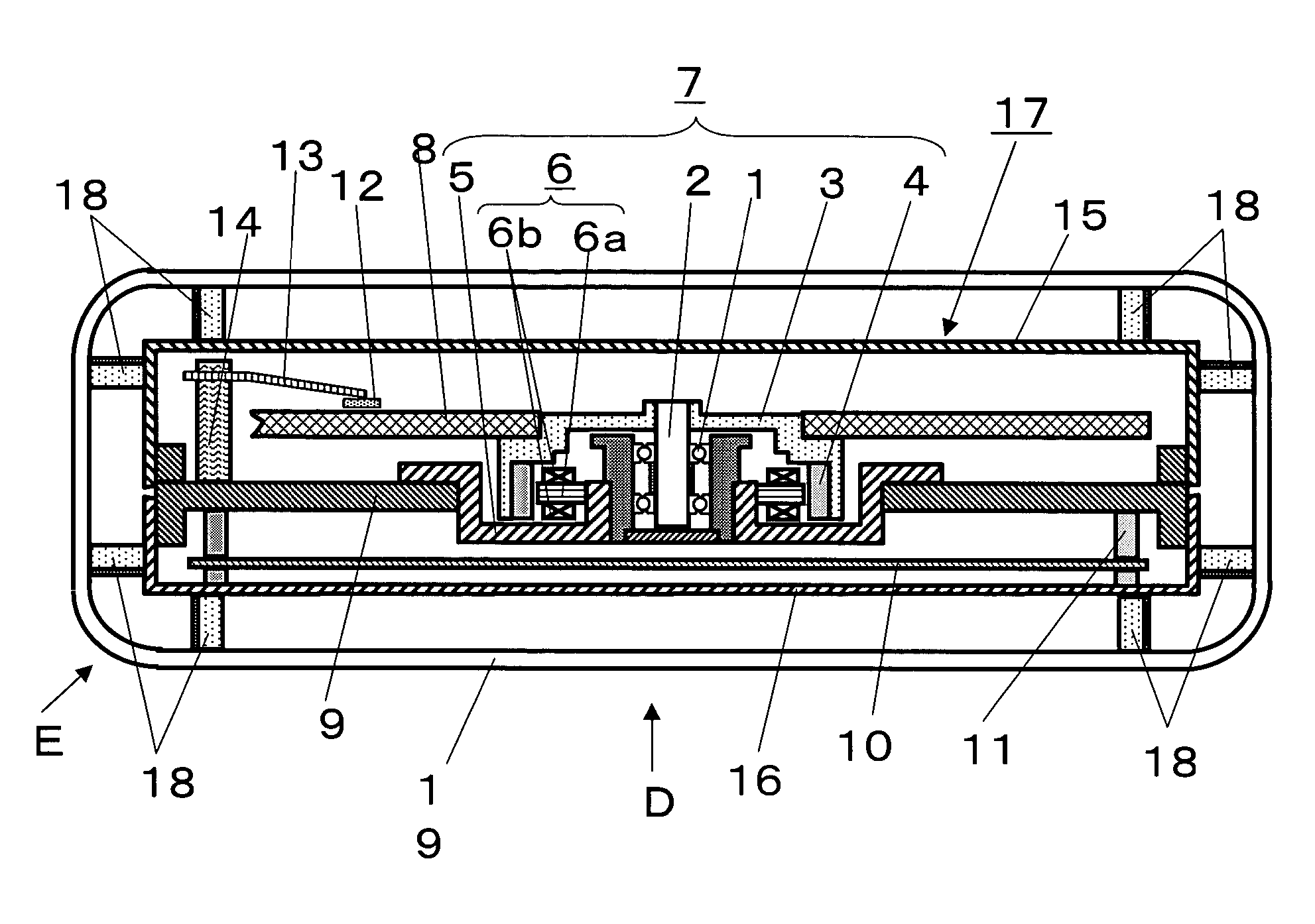
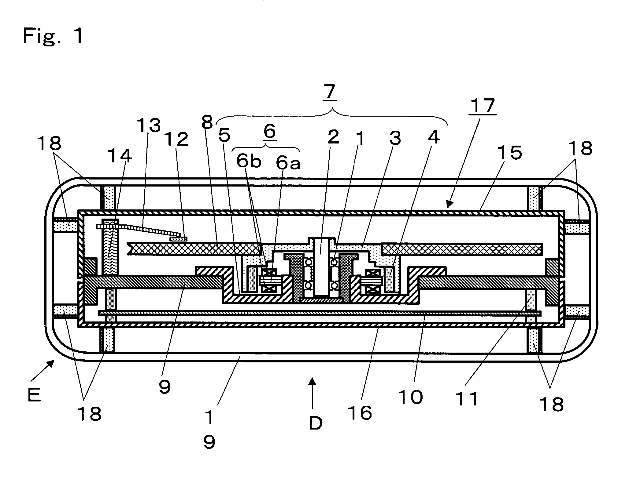
[0033]FIG. 1 is a schematic cross-sectional view showing a structure of main part of a disk drive having a shock-absorbing constitution, which is used here for explaining a shock absorbing method of electronic equipment in the preferred embodiment of the present invention. Explanation of electronic equipment will be made quoting a magnetic disk drive.

[0034]In FIG. 1, rotary magnet 4 magnetized to a plurality of magnetic poles is fixed to a lower inside-face of an outer periphery of rotor hub 3 by press-fitting, bonding or other well-known method. Rotor hub 3 is fixed to rotary shaft 2 rotatably supported by bearing 1. Stator 6 is fixed onto motor chassis 5 facing an inner peripheral face of rotary magnet 4, with stator 6 provided with stator core 6a having a plurality of pole-tooth parts, and each pole-tooth part is wound up by coil 6b. When current is ...


PUM

PropertyMeasurementUnit
angleaaaaaaaaaa
heightaaaaaaaaaa
flexibleaaaaaaaaaa

Abstract

Shock-absorbing member 18, a shock-absorbing method and an electronic device employing the member are disclosed, wherein the shock-absorbing member prevents electronic equipment main body from receiving a large shock and avoids a fatal damage to the equipment, even when the equipment is subjected to substantially a large impact of dropping of the equipment for instance. More specifically, shock absorbing member 18 is formed by integrally molding shock-absorbing base part 18a of resin material having a flexibility but having a certain degree of hardness and formed into a thin plate, and highly soft shock-absorbing base part 18a having a cushion capability, into a unit having a certain degree of thickness, wherein shock-absorbing base part 18a is thinner than shock-absorbing flexible part 18b, wherein shock-absorbing base part 18a bends when receiving an impact, and start absorbing the shock by buckling at a bending part thereof. Shock-absorbing member 18 is disposed on and fixed to electronic equipment main body, constituting the invention.

Description

TECHNICAL FIELD OF THE INVENTION[0001]The present invention relates to a shock-absorbing member, a shock-absorbing method using the absorbing member, and an electronic device adapting the member and the method, with the shock-absorbing member absorbing a shock applied to a disk type recording / reproducing device such as magnetic disk drive and optical disk drive recording and reproducing information in high density (hereinafter called a disk drive) and to other electronic devices used as portable equipment.BACKGROUND OF THE INVENTION[0002]Recently, electronic equipment such as a disk drive has been increasingly reduced in size and weight, and such electronic equipment is increasingly used as portable equipment. With this trend, chances for such portable electronic equipment to receive great shocks caused by dropping during its portable usage are also increasing. With further advancement of reduction in size and weight of devices, dropping height of a device during carriage tends to b...

Claims


Application Information

Patent Timeline
Patent Type & Authority Patents(United States)
IPC IPC(8): G11B5/012F16F1/02F16F3/12G11B33/08
CPCF16F1/02F16F3/12G11B33/08
Inventor KUWAJIMA, HIDEKI
Owner PANASONIC CORP
Why Eureka
Try Eureka