Device for clamping a roll of paper in a cutting machine

a technology of cutting machine and paper roll, which is applied in the direction of metal working apparatus, etc., can solve the problems of already known devices having some drawbacks in relation to the accuracy of the cut obtained, and getting worse, and achieves the effects of high cutting precision, reduced heat transmission, and high reliability of the devi

Pending Publication Date: 2022-11-03
UNICON ENG SRL
View PDF0 Cites 0 Cited by
  • Summary
  • Abstract
  • Description
  • Claims
  • Application Information

AI Technical Summary

Benefits of technology

[0011]A first advantage of the invention consists in the high cutting precision which is achieved by the reduction of heat transmitted towards the blade.
[0012]A second advantage consists in the high reliability of the device.
[0013]A further advantage is the reduction of energy consumption.
[0014]An even further advantage consists in the lower contamination of the paper log on the cut section thanks to the use of a lower quantity of lubricant.
[0015]A still further advantage consists in the reduced need for blade cooling and in the lengthening of the useful life of the blade, estimated at an increase of 10-15%.

Problems solved by technology

However, the already known devices have some drawbacks in relation to the accuracy of the cut obtained, which can get worse due to the movement of the two sections of the log and to the high heat that is generated during the cut and absorbed by the blade, which can be estimated at approximately 50% absorbed during cutting and 50% due to the contact of the paper with the blade after the cut, before the removal of the log portion cut to size.
The mere contact of the blade with the paper immediately after the end of the cut determines in fact an overheating of the blade with deformations and other negative effects, which are felt in particular for intensive use of the saw blade with high frequency of the cutting cycles.

Method used


Image

  • Device for clamping a roll of paper in a cutting machine
  • Device for clamping a roll of paper in a cutting machine
  • Device for clamping a roll of paper in a cutting machine

Examples


Embodiment Construction

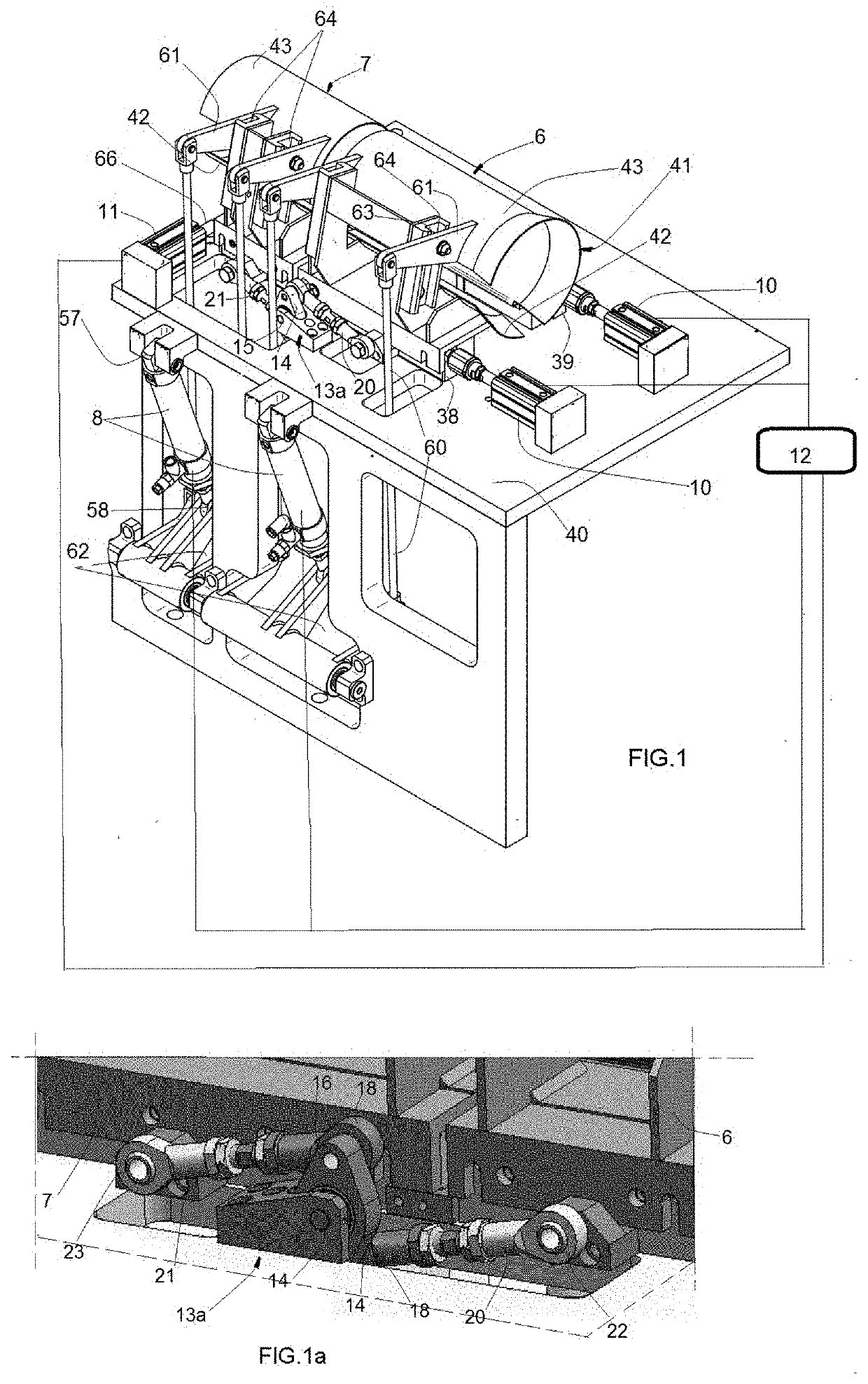
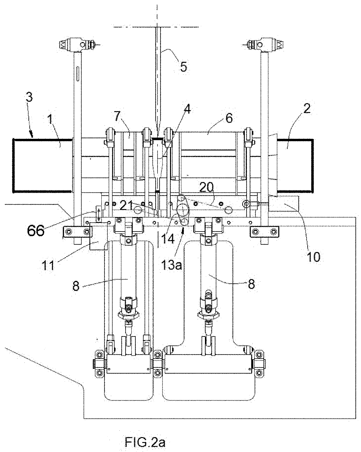
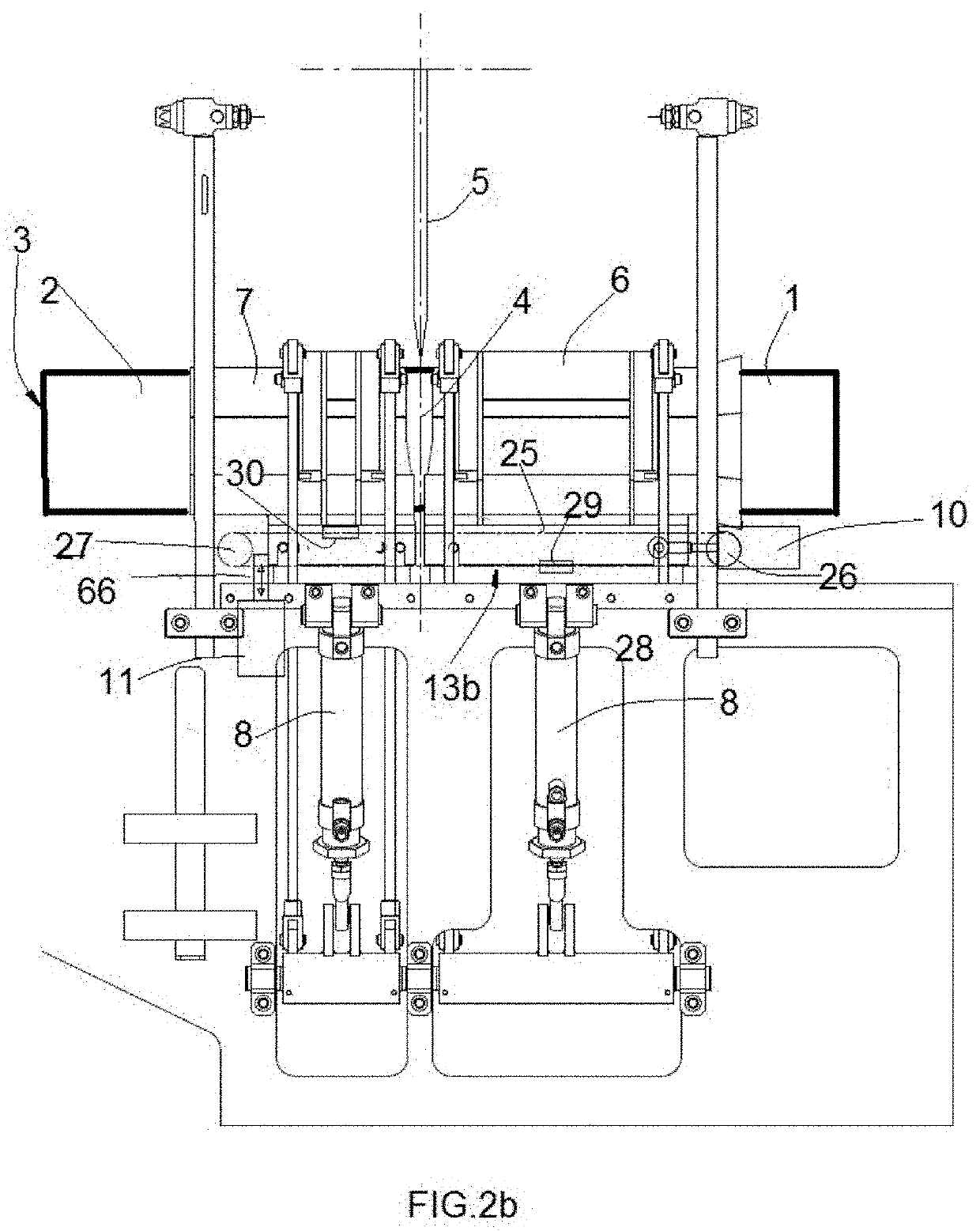
[0021]With reference to the drawings, a device for locking the adjacent sections 1, 2 of a roll of paper 3 cut off by the cutting blade 5 of a cutting machine M is described, schematically represented in FIG. 3.

[0022]The cutting machine M is of the conventional type and comprises a frame 50 in which a motor (not shown) is housed for driving, for example by means of a belt transmission 53, an arm 51 carrying the rotating cutting blade 5, and provided preferably of a sharpening unit 52 and counterweights 56, also of a conventional type.

[0023]In operation, the blade 5 follows an orbital cutting path during which the cutting edge of the blade advances inside the roll 3 along a cutting section plane 4, with the adjacent sections 1, 2 of the roll 3 arranged in a feed channel 55 and each held in position by gripping members, called clamping devices, 6, 7 which are positioned along the channel 55 slightly spaced upstream and downstream of the cutting plane defined by the movement of the bla...


PUM


Abstract

Device for locking two adjacent sections (1, 2) of a roll of paper (3) placed on the sides of a cutting section plane (4) defined by the movement of a cutting blade (5) of a cutting-off machine (M), comprising a pair of clamping devices (6, 7) configured to be able to assume an unlocking configuration with a locking configuration of respective sections (1, 2) of the roll (3); at least a first actuator (8) which can be operated on command to pass said clamping devices from the unlocking configuration to the locking configuration of the respective sections (1, 2), and vice versa; at least a second actuator (10) connected to the clamping devices (6, 7) and configured to perform a movement of reciprocal distancing of the clamping devices in a locking configuration with respect to said cutting section plane (4); means of inhibition (11) of the reciprocal moving away of the clamping devices active during the cutting advancement of the blade (5) through the roll (3); and activation means (12) of the second actuator (10) of the clamping devices (6, 7) configured to activate the reciprocal removal of the clamping devices immediately after the end of the roll cutting phase (3) performed by the blade (5).

Description

SECTOR OF THE INVENTION[0001]The invention relates to a device for locking in position a roll of paper during the cutting operation, i.e. of reducing a roll of tissue paper of greater length, called log, into rolls of shorter length.STATE OF THE ART[0002]For the same purpose, devices for cutting machines have been known for some time which block the log while an orbital blade cuts roll sections intended to form rolls of the desired length.[0003]These devices are provided with two locking members, called clamping devices, which tighten the two parts of the log at the sides of a cutting area where the blade of the cutting machine passes, which carries out the cut by advancing through the layers of the wound paper that forms the roll.[0004]Some known devices only have a blocking and unlocking movement of the roll and are controlled in such a way as to keep the roll sections still during cutting and release them after completion to allow the roll to advance along the feed channel of the...

Claims


Application Information

Patent Timeline
Patent Type & Authority Applications(United States)
IPC IPC(8): B26D3/16B26D7/02
CPCB26D3/16B26D7/02B26D2007/013B26D7/01B26D1/16
Inventor LUPI, LORENZO
Owner UNICON ENG SRL
Why Eureka
Try Eureka