Technique for filling bearing clearance of fluid-dynamic-pressure bearing unit with oil

a technology of fluid-dynamic-pressure bearings and oil, which is applied in the direction of magnetic recording, rotary piston liquid engine, record information storage, etc., can solve the problems of drop-off in productivity, endurance and reliability of the motor, and the inability to artificially create a perfect vacuum sta

Active Publication Date: 2008-03-18
NIDEC CORP
View PDF4 Cites 10 Cited by
  • Summary
  • Abstract
  • Description
  • Claims
  • Application Information

AI Technical Summary

Benefits of technology

[0015]An object of the present invention is to obviate problems originating in air bubbles being generated within oil charged into the bearing clearances in fluid-dynamic-pressure bearing units, before such problems occur. More specifically, an object of the invention is to make available a method of manufacturing fluid-dynamic-pressure bearing units, and a motor utilizing the fluid-dynamic-pressure bearing units, in which preventing the generation of air bubbles in the course of an oil-charging operation equivalent to a step following the degassing operation is made possible, and in which specifying the causative source of air bubbles in instances in which the generation of air bubbles is detected is made possible.
[0016]With a method according to the present invention of manufacturing a fluid-dynamic-pressure bearing, in an implementation in which a degassing process done by vacuum-degassing and stirring-degassing is carried out, a drive source for rotating a stirrer is arranged on the exterior of the vacuum chamber and the stirrer is indirectly rotated, whereby a special configuration for maintaining a hermetic seal on the vacuum chamber is rendered unnecessary. This enables the configuration of the apparatus to be simplified and facilitates management of the hermetic sealing quality.
[0017]What is more, by having the reduced-pressure level of the interior of the vacuum chamber storing the oil that has undergone a degassing process—of the oil tank and associated components, which are a vacuum chamber located upstream in terms of the oil-charging procedure—be greater (in other words, in a higher vacuum condition) than the reduced-pressure level within the vacuum chamber for oil-charging, which is located downstream, in terms of the procedure, from the oil-storing vacuum chamber, then even should the charging operation be carried out with oil in which a trace amount of air is still dissolved, the air bubbles will not foam during the procedure and become manifest. These aspects of the invention thus enable the oil-charging procedure to be carried out smoothly.
[0019]In a further aspect of the present invention, by preparatorily heating the oil when vacuum-degassing and stirring-degassing are carried out, the viscosity of the oil is lowered so that the degassing is expedited, which enables the oil-degassing process to be carried out more efficiently and reliably. An additional benefit is that heating the oil enables volatile impurities contained in the oil to be removed.
[0020]Should air have gotten mixed into the oil in an oil-charged fluid-dynamic-pressure bearing unit once it has been incorporated into a motor, then if repeated starting and stopping of the motor gives rise to an elevation of the oil boundary surface within the bearing clearances, or if, while the starting / stopping of the motor is repeatedly carried out, the extent to which the oil boundary surface is elevated increases, either way it will be clear that the basis of the in-mixing of air into the oil lies in the rotation of the motor; in other words, it will be evident that the in-mixing of air continues to occur inasmuch as there is a problem with the structure or processing of the fluid-dynamic-pressure bearing unit. In such instances, simultaneously implementing a plurality of degassing techniques so that the oil-degassing process is carried out with maximal reliability, and meanwhile maintaining the reduced-pressure level of the oil-storing vacuum chamber relative to the reduced-pressure level of the oil-charging vacuum chamber at the relationship described above will at least make it clear that air remnant in or mixed into the oil is not due to some deficiency in the oil-charging operation that includes the degassing process step. Thus, inasmuch as the potential factors giving rise to the problem are narrowed down to a defect in either the structure or processing of the fluid-dynamic-pressure bearing unit, singling out the causative source is facilitated, enabling prompt testing to establish appropriate measures to address the problem, and enabling the implementation of those measures.

Problems solved by technology

This is thought to originate in air, slight though it may be, remaining dissolved within the oil even after having undergone the degassing process, because even with the vacuum chamber being pumped down to a vacuum level, artificially creating a perfect vacuum state is impossible.
Air bubbles becoming manifest during the oil-charging procedure can hinder the smooth supply of oil from the vacuum chamber that stores oil to the vacuum chamber that holds the bearing unit, or, at the stage in which the oil has arrived inside the vacuum chamber that holds the bearing unit, can foam the oil such that the oil spouts out and sticks to the bearing unit and the vacuum-chamber interior, making it necessary to wipe the oil off, and such consequences cause a drop-off in productivity.
Moreover, if the motor is run with air bubbles within the oil mixed in as they are, eventually either of two of the following problems will arise.
One affects the endurance and reliability of the motor and is a problem of the air bubbles expanding in volume-due, for example, to a rise in temperature-and causing the oil to leak out to the bearing-unit exterior.
The other affects the rotational precision of the motor and is a problem of incidents of vibration or a problem of deterioration from NRRO (non-repeatable runout), due to the air bubbles coming into contact with the dynamic-pressure-generating grooves provided in the bearings.
Additional problems with the bearing oil-charging method discussed above involve a stirring propeller within the oil stored inside the vacuum chamber.
If the portion of the vacuum chamber through which the shaft passes is not hermetically sealed, then when the propeller is rotated to agitate and degas the oil, leaking of oil and dissolving of air into the oil will occur.
The occurrence of such problems creates management difficulties.
Furthermore, in that simply stirring the oil by the rotation of the propeller alone entails an extremely lengthy degassing operation in order to purge the oil completely of the air dissolved into it, a further concern is the consequent loss in productivity in the manufacture of fluid-dynamic-pressure bearing units.
In such instances, given that it is unclear whether the generated air bubbles remain from or were mixed in during the oil-charging procedure, or became freshly mixed-in within the oil from the motor being driven, it is difficult to single out whether the cause is an operational shortcoming in the oil-charging procedure, or is a structural defect in, or a machining-operational shortcoming in the production of, the fluid-dynamic-pressure bearing units themselves.
The consequence is that inspecting / testing to determine the cause and then finding the most appropriate way to eliminate the in-mixing of air into the oil requires an inordinate amount of time.

Method used


Image

  • Technique for filling bearing clearance of fluid-dynamic-pressure bearing unit with oil
  • Technique for filling bearing clearance of fluid-dynamic-pressure bearing unit with oil
  • Technique for filling bearing clearance of fluid-dynamic-pressure bearing unit with oil

Examples


Embodiment Construction

[0024]The object of obviating problems originating in air bubbles being generated within oil charged into the bearing clearances in fluid-dynamic-pressure bearing units, before such problems occur, was realized without increasing operational man-hours needed or complicating the operational steps. The invention also accomplished the other object, which is to make it possible to single out the causative source of air bubbles in instances in which the generation of air bubbles is detected, without increasing man-hours needed or complicating the steps in the process.

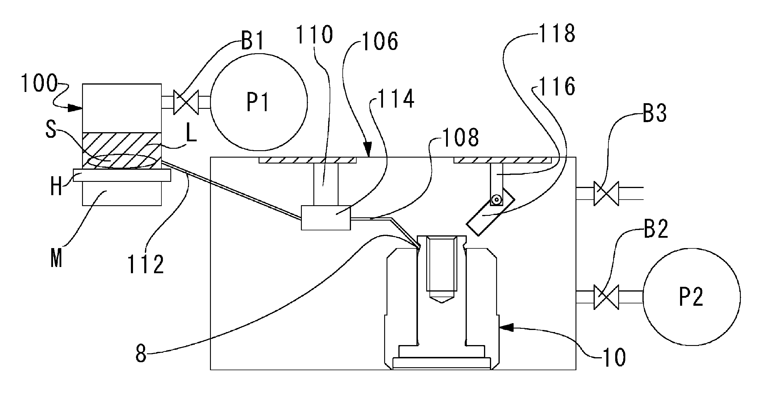
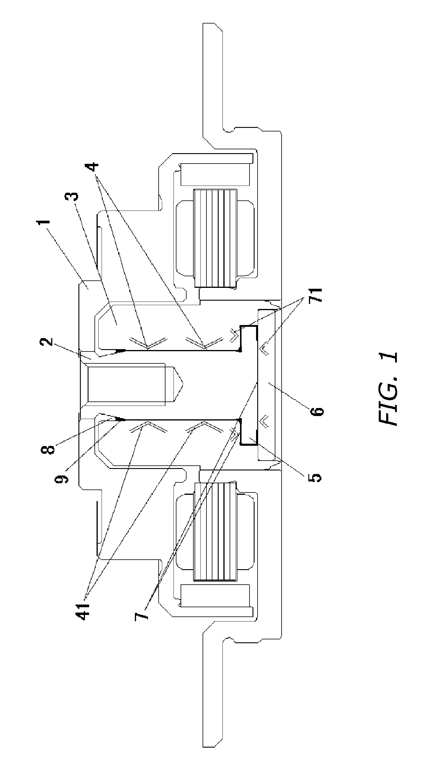
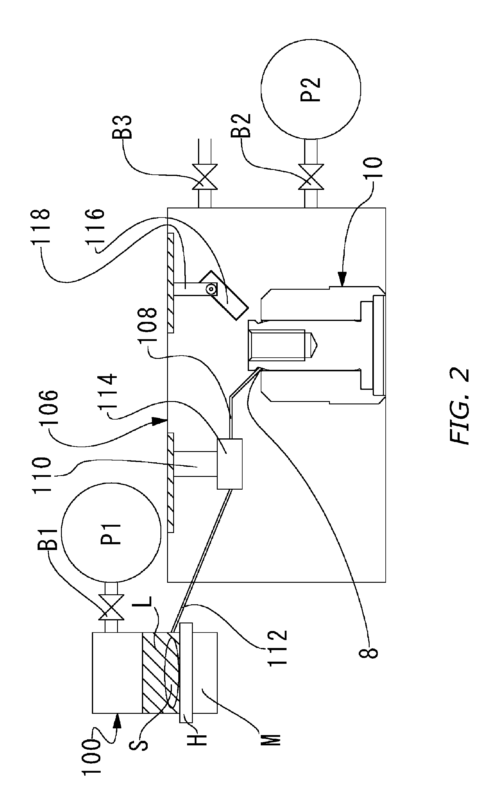
[0025]Below, reference is made to the appended drawings to discuss a method of manufacturing fluid-dynamic-pressure bearing units according to the present invention. A fluid-dynamic-pressure bearing unit 10 has the same configuration as the fluid-dynamic-pressure bearing shown in FIG. 1 and therefore, the configuration thereof is not elaborated upon to avoid repetitive description.

[0026]In a method according to the present e...


PUM

PropertyMeasurementUnit
vacuum pressureaaaaaaaaaa
temperatureaaaaaaaaaa

Abstract

Fluid-dynamic-pressure bearing manufacturing method for more efficient and fail-safe degassing of bearing oil. Method makes it possible to prevent the generation of air bubbles in the course of an oil-charging operation that amounts to a step following degassing, and to single out the causative source of air bubbles when their generation has been detected. At the same time oil that is under a reduced-pressure environment within an oil-storing vacuum chamber is vacuum-degassed, immersed within the oil a stirrer for agitating and degassing the oil is rotated by indirect drive means, and the oil after having been degassed is supplied to a vacuum chamber where a fluid-dynamic-pressure bearing unit is retained—which has been pumped down to a pressure below the pressure within the oil-storing vacuum chamber—and is charged into the bearing clearances by raising the internal pressure of the bearing-retaining vacuum chamber.

Description

BACKGROUND OF THE INVENTION[0001]1. Technical Field[0002]The present invention relates to methods of manufacturing fluid-dynamic-pressure bearing units employed as bearing devices in applications such as spindle motors for hard-disk drives, and to motors employing such fluid-dynamic-pressure bearing units.[0003]2. Description of the Related Art[0004]As bearings for motors in which high rotational precision is demanded—as is the case with spindle motors employed in disk drives that drive recording disks such as hard disks, and with motors for driving the polygonal mirrors of laser printers—in order to support the shaft and sleeve letting one rotate relative to the other, fluid-dynamic-pressure bearing units that employ the fluid pressure of a lubricant such as oil intervening in between the two have variously been proposed to date.[0005]One example of a motor that employs such fluid-dynamic-pressure bearing units is illustrated in FIG. 1. This conventional dynamic-pressure-bearing em...

Claims


Application Information

Patent Timeline
Patent Type & Authority Patents(United States)
IPC IPC(8): B21D53/10B65B43/42B67C3/00F16C17/10F16C33/10F16C33/14G11B19/20H02K7/08
CPCF16C17/107F16C33/107Y10T29/49639Y10T29/49636Y10T29/49702F16C2370/12
Inventor SUMI, SHIGEHARUHIROSHI, JYOICHIANDO, HIRONORI
Owner NIDEC CORP
Why Eureka
Try Eureka