
Electric lamp with heat resistant shade

a technology of heat-resistance shade and electric lamp, which is applied in the direction of lighting device details, lighting support devices, lighting and heating apparatus, etc., can solve the problems of high thermal load of plastic walls, increased production costs, and increased production costs, and achieves easy adjusting, considerable air resistance, and high heat-resistance

Inactive Publication Date: 2008-03-18
GENERAL ELECTRIC CO
View PDF15 Cites 0 Cited by
  • Summary
  • Abstract
  • Description
  • Claims
  • Application Information

AI Technical Summary

Benefits of technology

"The invention provides an electric lamp with a heat-resistant shade made of heat-resistant plastic foil. The shade has a conical shape with a smaller diameter at the first end and a larger diameter at the second end. The first end is inserted into a fixing gap around the common axis of the lamp base and the envelope. The shade is elastic and can be tailored for optical and visual features. The lamp has a lightweight upper part and a shock-resistant shipping design. The technical effects of the invention include improved heat resistance, flexibility in optical and visual features, reduced likelihood of lamp breaking, and a simplified and cost-effective manufacturing process."

Problems solved by technology

This construction uses plastic that is less fragile, however, the molding procedure is an expensive technology when shapes following different demands are quickly changed.
If the radiation flux at the reflecting wall is high, the thermal load of the plastic wall is considerable and the danger of softening may occur.
This reflector eliminates the excess thermal load, but the quite large plastic reflector element can easily be damaged.
The molding technology of the reflector makes also this construction expensive as well.

Method used


Image

  • Electric lamp with heat resistant shade
  • Electric lamp with heat resistant shade
  • Electric lamp with heat resistant shade

Examples


Embodiment Construction

[0027]The same functional elements of different embodiments in the drawings are identified by the same reference numbers.

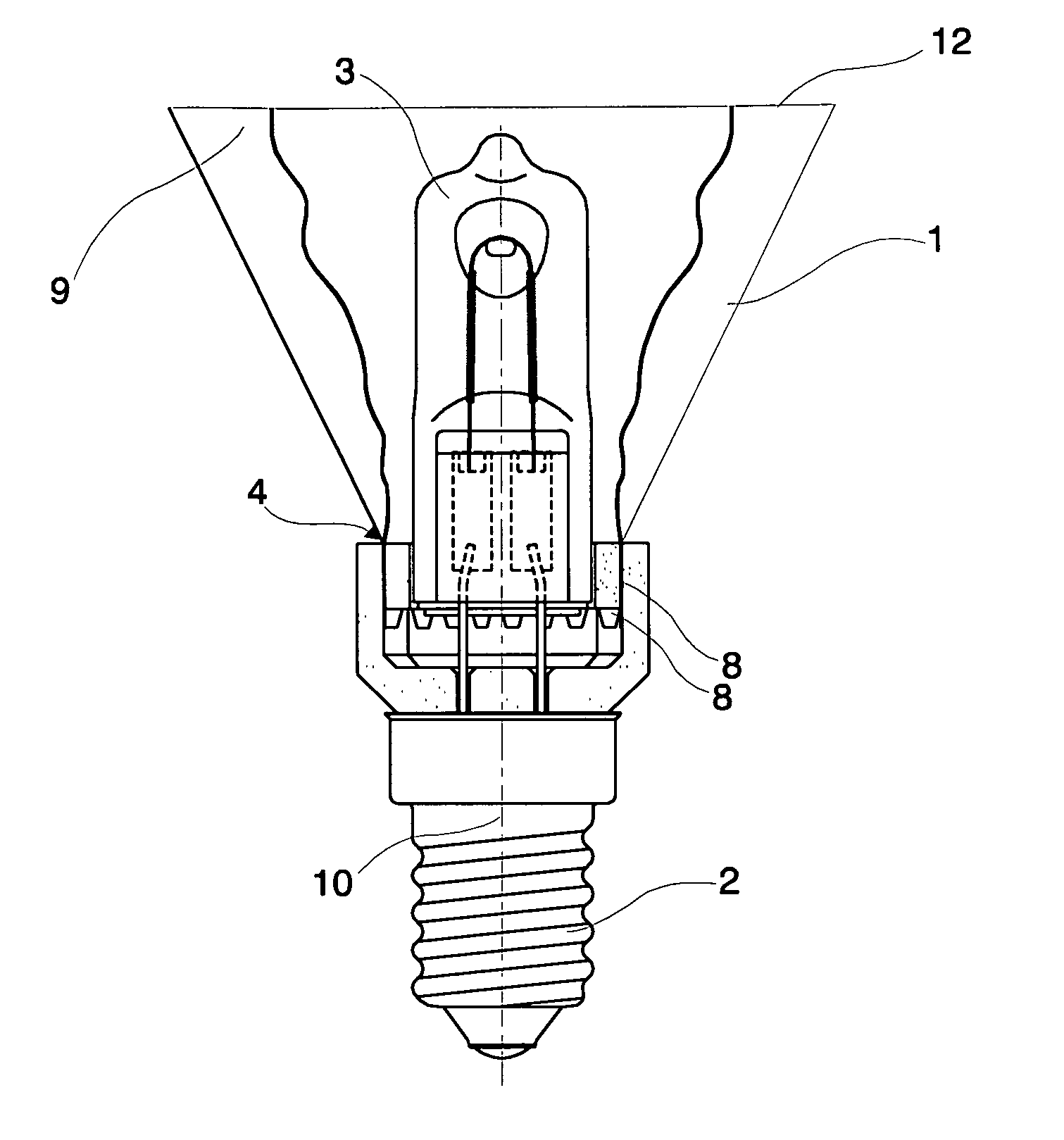
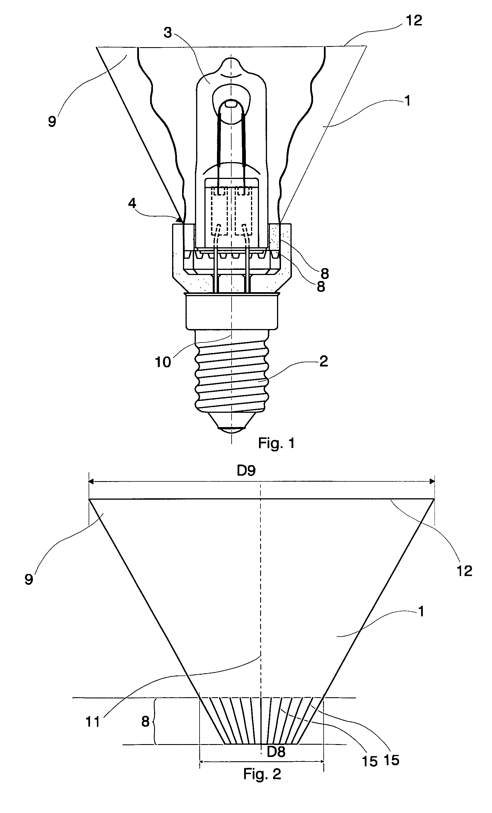
[0028]In FIG. 1, an exemplary embodiment of the invention is shown, as a halogen lamp with a heat resistant shade 1. The exemplary halogen lamp is mounted with a lamp base 2, an envelope 3, and a ceramic support member 4 is disposed between them. An elastic shade 1 of substantially conical shape is mounted around the envelope 3. A substantially conical shape in the context of the present specification means a frustum-conical shape, a slightly conical, almost cylindrical shape as well as a broadening curved shape including a paraboloidal shape. A curved shape can be manufactured, for example, by pressing technology.

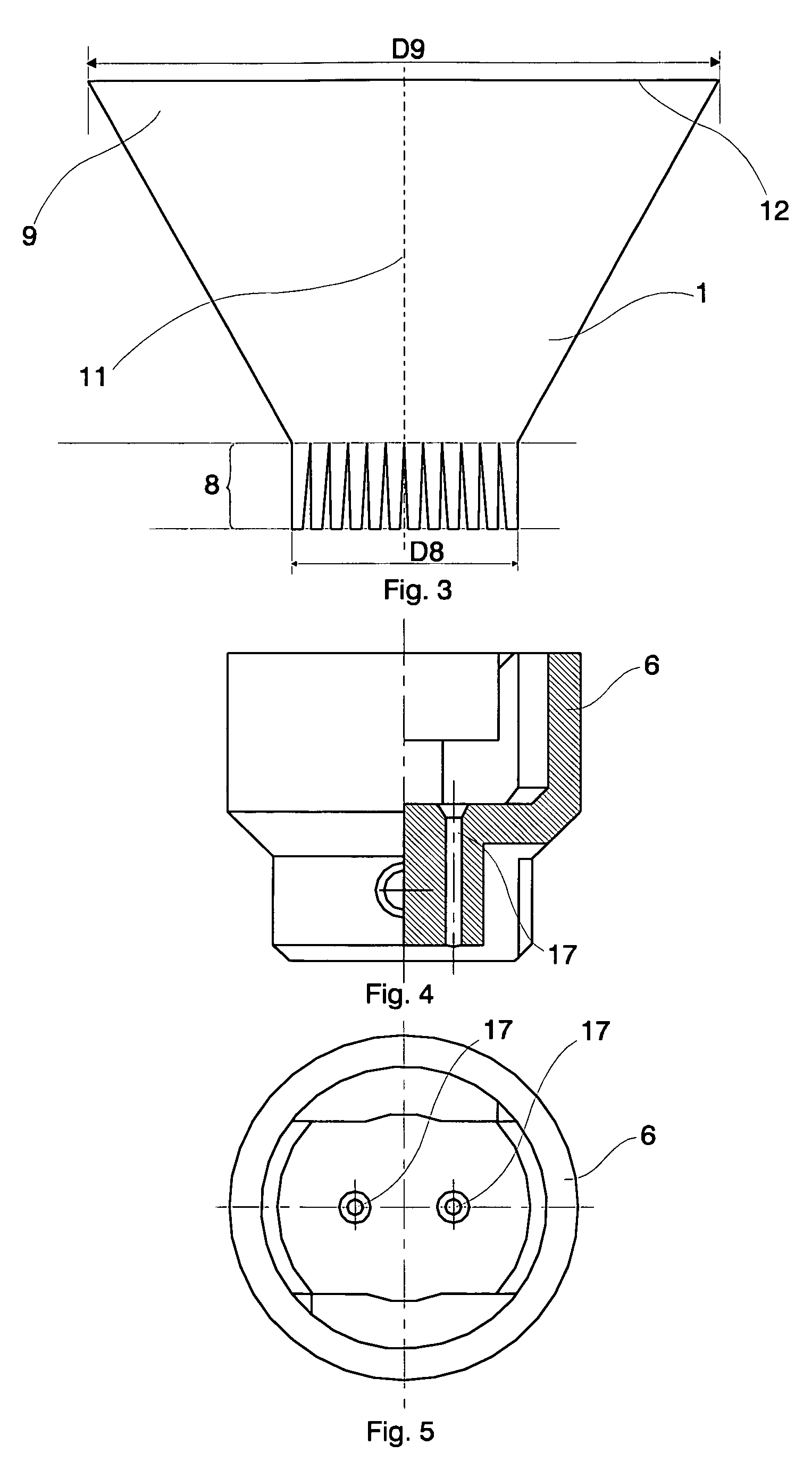
[0029]The lamp base 2 and the envelope 3 have a common axis 10, which substantially coincides with the axis of the shade 1 that has a frustum-conical shape in FIG. 1. There is a fixing gap 7 within the ceramic support member 4, which extends around the a...


PUM


Abstract

An electric lamp comprises a lamp base and an envelope having a common axis, a support member having a fixing gap around the common axis, and an elastic shade of substantially conical shape. The shade has a first end portion inserted in the fixing gap and a second end portion remote from the lamp base. The diameter of the first end portion taken perpendicularly to said axis is smaller than the diameter of the second end portion, and the elastic shade is made of heat resistant plastic foil.

Description

BACKGROUND OF THE INVENTION[0001]This invention relates to an electric lamp with heat resistant shade.[0002]In case of different lamps mounted with electric burner, a glass reflector structure is used, in which the light-directing feature is provided for by a side-wall of the reflector covered by a metallic layer. The glass side-wall of the reflector ends in a plane or convex front wall, in other words the reflector has a lens for emitting the light beam. The glass reflector constitutes a rigid, fragile structure.[0003]U.S. Pat. No. 4,548,589 discloses a halogen bulb lamp assembly manufactured by mounting a previously aligned halogen bulb unit in a one-piece molded plastic rectangular reflector with a mirrorized paraboloidal inner surface. The halogen bulb unit has a pair of spaced connector pins that are coated with an epoxy adhesive and inserted into a pair of stepped through bores in the reflector. This construction uses plastic that is less fragile, however, the molding procedur...

Claims


Application Information

Patent Timeline
Patent Type & Authority Patents(United States)
IPC IPC(8): F21V11/00
CPCF21V17/04F21V21/22
Inventor CSEH, GEZANAGY, PETER LAJOS
Owner GENERAL ELECTRIC CO
Learn More