
Keyboard with key supporting structure for portable electronics devices

a portable electronic device and key support technology, applied in the direction of substation equipment, contact mechanisms, contacts, etc., can solve the problems of limiting the freedom to design the keyboard assembly independently, increasing the power consumption, etc., and achieve the effect of simplifying the structure and highlighting the keys

Inactive Publication Date: 2008-03-18
NOKIA TECH OY
View PDF10 Cites 33 Cited by
  • Summary
  • Abstract
  • Description
  • Claims
  • Application Information

AI Technical Summary

Benefits of technology

The invention provides a light guide structure for keyboard assemblies that is simple and integrated, supporting the keyboard assembly and protecting the keys from mechanical stress. The structure includes an elastic member for the keys and a rigid member for separating the keys and protecting them from mechanical stress. The rigid member also guides the light from a light source to illuminate the keys. The combined structure of the elastic and rigid members forms a single-piece element, improving the mechanical robustness of the keyboard assembly and allowing for a more flexible layout. The invention also reduces the number of light sources needed and contributes to smaller power consumption, savings in material and production costs.

Problems solved by technology

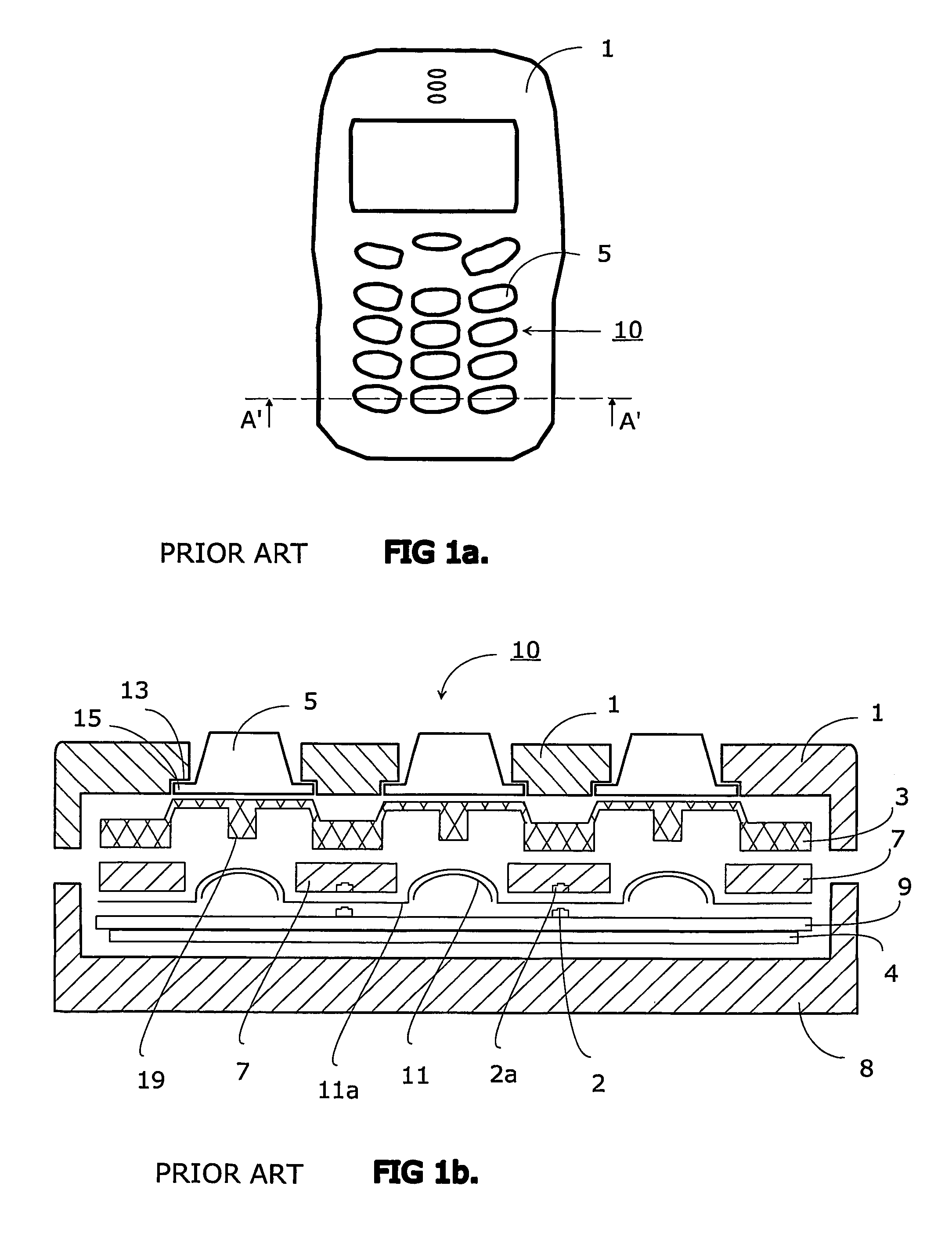
In addition, LEDs 2 are rather power consuming components which means that the larger the number of LEDS 2, the larger the power consumption.
In addition, prior art keyboard assemblies provided with openings in the cover part 1 to support the whole combination of keyboard assembly 10 as described above, will limit the freedom to design keyboard assemblies independently, because the layout design of the cover part is bound up with the layout design of the keyboard.

Method used


Image

  • Keyboard with key supporting structure for portable electronics devices
  • Keyboard with key supporting structure for portable electronics devices
  • Keyboard with key supporting structure for portable electronics devices

Examples


Embodiment Construction

[0032]A description of FIGS. 1a and 1b was given earlier in connection with the description of the state of the art.

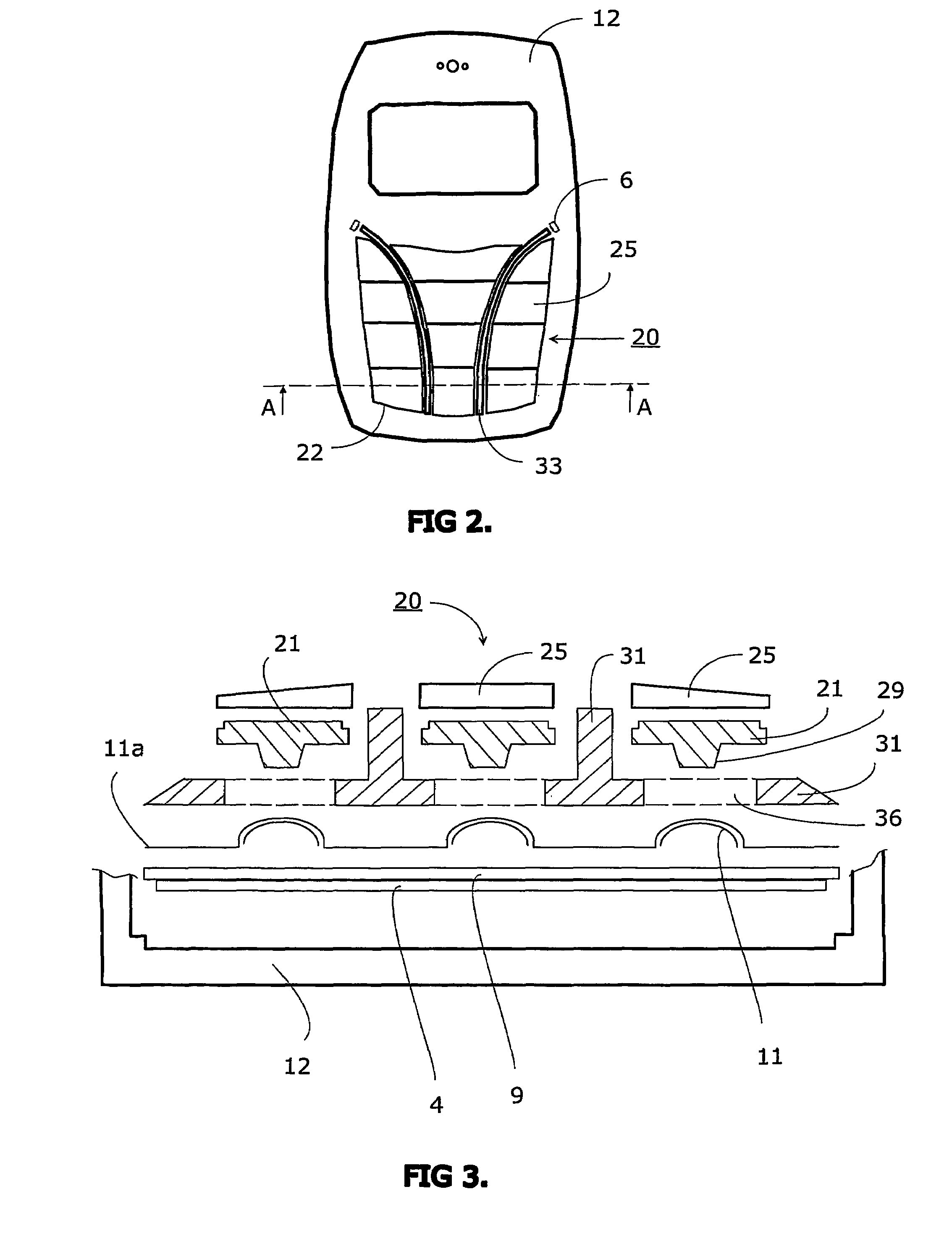
[0033]Referring to FIG. 2 there is shown an embodiment of a communication device according to the invention comprising a cover 12, keyboard assembly 20 with a plurality of keys, key tops 25, protection ribs 33 and an exemplary location of a light source 6 under the cover in dashed line. All these components mentioned above are discussed more detail later in this description. Still referring to FIG. 2 there is shown a dashed line A-A to depict an exemplary cutting line along which is constituted an exemplary cross-section diagram of the keyboard assembly 20 according an embodiment of the invention in FIGS. 3 and 4.

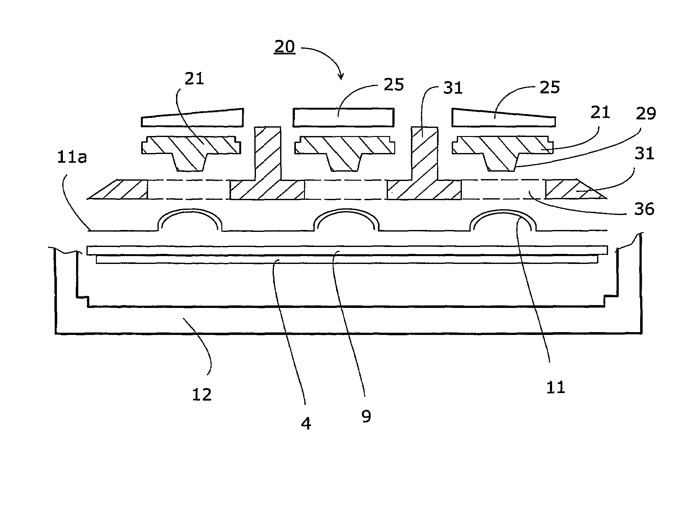
[0034]FIG. 3 shows an exploided view of a keyboard assembly 20 which is provided with a layer of elastic material 21, preferably in a sheet-like form, which forms a basis for an array of keys and for individual keys therein. The elastic material layer 21, pref...


PUM


Abstract

A keyboard assembly (20) has a light guide (23, 31, 33) and a supporting structure (23, 33) arranged to provide an illuminated and integrated keyboard assembly (20). A light guide (23, 31, 33) provides an integrated supporting, protecting and illuminating structure for keyboard assemblies (20). The keyboard assembly (20) has a layer of rigid material (31) which separates the elastic layer (21) from the printed wired board (9) located under the rigid layer (31). The layers are bonded together. The protection rib (33) is part of the combination of the elastic layer (21) and rigid layer (31) which is supported against the printed wired board (9) by the rigid layer (31). The combined structure of the light guide and supporting frame forms an integrated structure (23, 31, 33) which illuminates an array of keys (22), supports the keyboard assembly (20) and protects the keys (22) and key tops 25 from mechanical stress.

Description

CROSS REFERENCE TO RELATED APPLICATIONS[0001]This application is for entry into the U.S. national phase under §371 for International Application No. PCT / FI2003 / 000793 having an international filing date of Oct. 23, 2003, and from which priority is claimed under all applicable sections of Title 35 of the United States Code including, but not limited to, Sections 120, 363 and 365(c).TECHNICAL FIELD OF THE INVENTION[0002]This invention relates generally to a keyboard assembly of a portable electronic device, and more particularly to a keyboard assembly in which a light guide and a supporting and protecting structure are arranged to provide an illuminated and integrated keyboard assembly. This invention also relates to a light guide therefor.BACKGROUND OF THE INVENTION[0003]A keyboard and particularly key buttons or keys of the keyboard are typically backlit so that the user can see the keys and particularly symbols or legends on top of the keys in dark conditions, too. It is known that...

Claims


Application Information

Patent Timeline
Patent Type & Authority Patents(United States)
IPC IPC(8): H01H13/70G06F3/02H01H13/702H04M1/22H04M1/23H04M1/724H04Q7/22
CPCH01H13/702H04M1/22H04M1/23H01H2219/062H01H2231/022H04M1/72519H04M1/724
Inventor HAKUNTI, JUSSILAITINEN, MIKKO
Owner NOKIA TECH OY
Learn More