Horizontal emitting, vertical emitting, beam shaped, distributed feedback (DFB) lasers by growth over a patterned substrate
What is AI technical title?
AI technical title is built by Patsnap AI team. It summarizes the technical point description of the patent document.
a technology of horizontal and vertical emission and lasers, applied in lasers, semiconductor devices, semiconductor lasers, etc., can solve the problems of difficult manufacturing of nitride lasers, difficult cleavage, and difficult to obtain the properties of vertical emission,
Inactive Publication Date: 2008-03-18
RGT UNIV OF CALIFORNIA
View PDF41 Cites 24 Cited by
Summary
Abstract
Description
Claims
Application Information
AI Technical Summary
This helps you quickly interpret patents by identifying the three key elements:
Problems solved by technology
Method used
Benefits of technology
Problems solved by technology
Unfortunately, besides huge materials challenges, nitride lasers are difficult to manufacture.
In addition, cleavage is hard to achieve because a sapphire substrate is typically used with nitride lasers.
However, these properties, especially vertical emission, are extremely hard to obtain, as the high quality mirrors required for vertical cavity surface-emitting lasers (VCSELs) prove extremely difficult to manufacture.
Method used
Image
Click on the blue label to locate the original text in one second.
Reading with bidirectional positioning of images and text.
Examples
Embodiment Construction
[0030]In the following description of the preferred embodiment, reference is made to the accompanying drawings which form a part hereof, and in which is shown by way of illustration a specific embodiment in which the invention may be practiced. It is to be understood that other embodiments may be utilized and structural changes may be made without departing from the scope of the present invention.
[0031]Overview
[0032]The present invention describes new laser structures created using simplified fabrication processing. The simplified fabrication processing preferably comprises planar fabrication processing, which means that the laser structures can be easily manufactured at low cost.
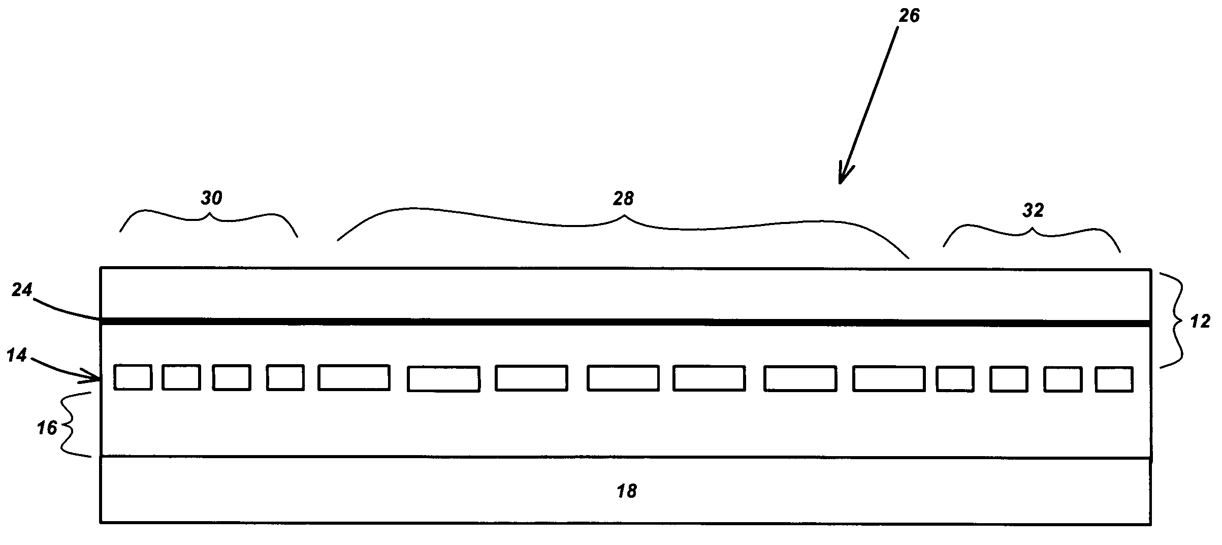
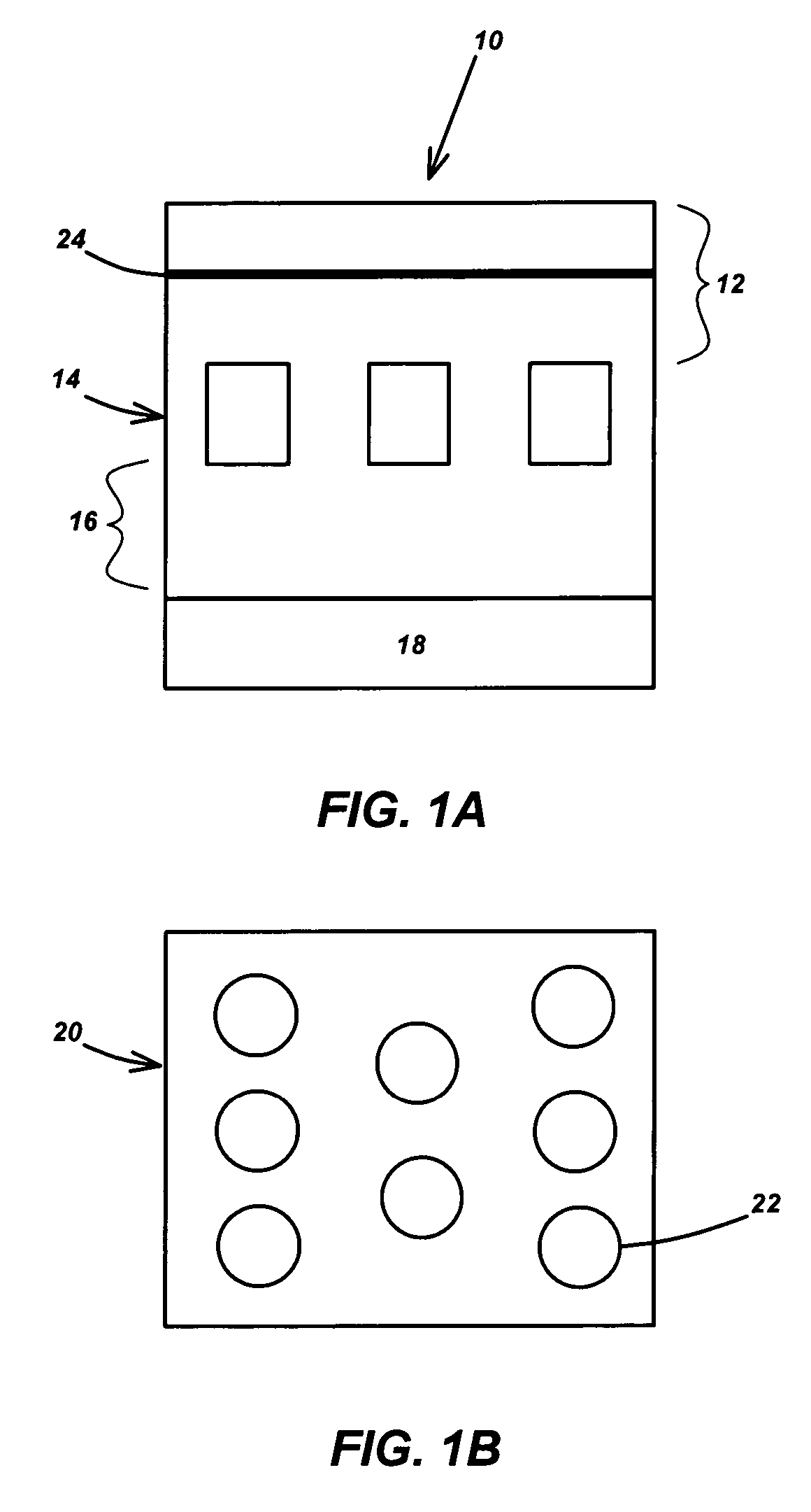
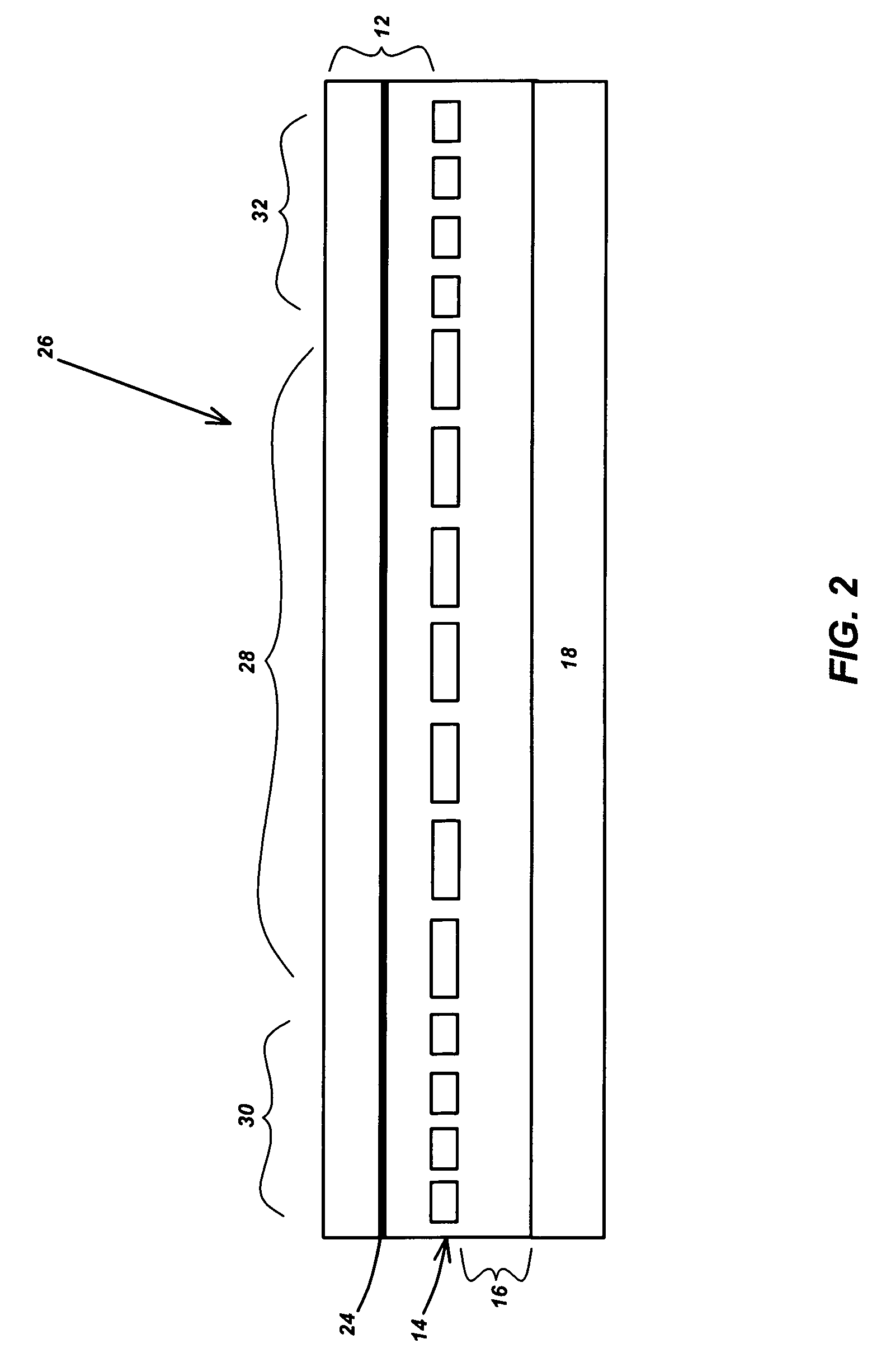
[0033]Preferably, the laser structure is comprised of a substrate, a buffer layer grown on the substrate, one or more patterned layers deposited on the buffer layer and comprising a patterned, perforated or pierced mask (made of insulating, semiconducting or metallic material) and materials filling holes in...
PUM
Abstract
A structure using integrated optical elements is comprised of a substrate, a buffer layer grown on the substrate, one or more patterned layers formed on the buffer layer and one or more active layers formed on or between the patterned layers, for instance by Lateral Epitaxial Overgrowth (LEO), and including one or more light emitting species. The patterned layer comprises a mask (made of insulating, semiconducting or metallic material) and material filling holes in the mask. The patterned layer, due to a large index difference with the active layer and / or variations of a refractive index between the mask and materials filling holes in the mask, acts as an optical confinement layer, a mirror, a diffraction grating, a wavelength selective element, a beam shaping element or a beam directing element.
Description
CROSS-REFERENCE TO RELATED APPLICATIONS[0001]This application is related to the following and commonly-assigned applications:[0002]U.S. application Ser. No. 10 / 938,704, filed Sep. 10, 2004, by Carole Schwach, Claude C. A. Weisbuch, Steven P. DenBaars, Henri Benisty, and Shuji Nakamura, entitled “WHITE, SINGLE OR MULTI-COLOR LIGHT EMITTING DIODES BY RECYCLING GUIDED MODES,”[0003]U.S. application Ser. No. 11 / 067,910 filed on Feb. 28, 2005, by Claude C. A. Weisbuch, Aurelien J. F. David, James S. Speck and Steven P. DenBaars, entitled “Single or multi-color high efficiency LIGHT EMITTING DIODE (LED) by growth over a patterned substrate,” and,[0004]U.S. application Ser. No. 11 / 067,956, filed on Feb. 28, 2005, by Claude C. A. Weisbuch, Aureien J. F. David and Steven P. DenBaars, entitled “HIGH EFFICIENCY LIGHT EMITTING DIODE (LED) WITH OPTIMIZED PHOTONIC CRYSTAL EXTRACTOR,”STATEMENT REGARDING SPONSORED RESEARCH AND DEVELOPMENT[0005]The present invention was made under support from the Un...
Claims
Application Information
Patent Timeline
Application Date:The date an application was filed.
Publication Date:The date a patent or application was officially published.
First Publication Date:The earliest publication date of a patent with the same application number.
Issue Date:Publication date of the patent grant document.
PCT Entry Date:The Entry date of PCT National Phase.
Estimated Expiry Date:The statutory expiry date of a patent right according to the Patent Law, and it is the longest term of protection that the patent right can achieve without the termination of the patent right due to other reasons(Term extension factor has been taken into account ).
Invalid Date:Actual expiry date is based on effective date or publication date of legal transaction data of invalid patent.

