Optical delay line to correct phase errors in coherent ladar

a phase error and optical delay technology, applied in the field of laser systems, can solve the problems of limiting the component requirements that cannot be met using conventional ladar systems, and the limitation of the signal fidelity that can be achieved

Active Publication Date: 2008-03-18
RAYTHEON CO
View PDF12 Cites 16 Cited by
  • Summary
  • Abstract
  • Description
  • Claims
  • Application Information

AI Technical Summary

Problems solved by technology

However, the increasing demand for fidelity, resolution, and long range of operation make the component requirements impossible to meet using conventional ladar systems.
Laser transmitters, as other transmitters, tend to drift frequency in time, creating a limitation on the signal fidelity that can be achieved.
In addition, large time-bandwidth modulated transmitted waveforms also require a high degree of phase control and ultimately also limit the return signal fidelity that can be achieved.
Conventional ladar systems cannot meet the component stability requirements (laser transmitter stability and modulator linearity) necessary for high fidelity, high resolution, long range applications.

Method used


Image

  • Optical delay line to correct phase errors in coherent ladar
  • Optical delay line to correct phase errors in coherent ladar
  • Optical delay line to correct phase errors in coherent ladar

Examples


Embodiment Construction

[0015]Illustrative embodiments and exemplary applications will now be described with reference to the accompanying drawings to disclose the advantageous teachings of the present invention.

[0016]While the present invention is described herein with reference to illustrative embodiments for particular applications, it should be understood that the invention is not limited thereto. Those having ordinary skill in the art and access to the teachings provided herein will recognize additional modifications, applications, and embodiments within the scope thereof and additional fields in which the present invention would be of significant utility.

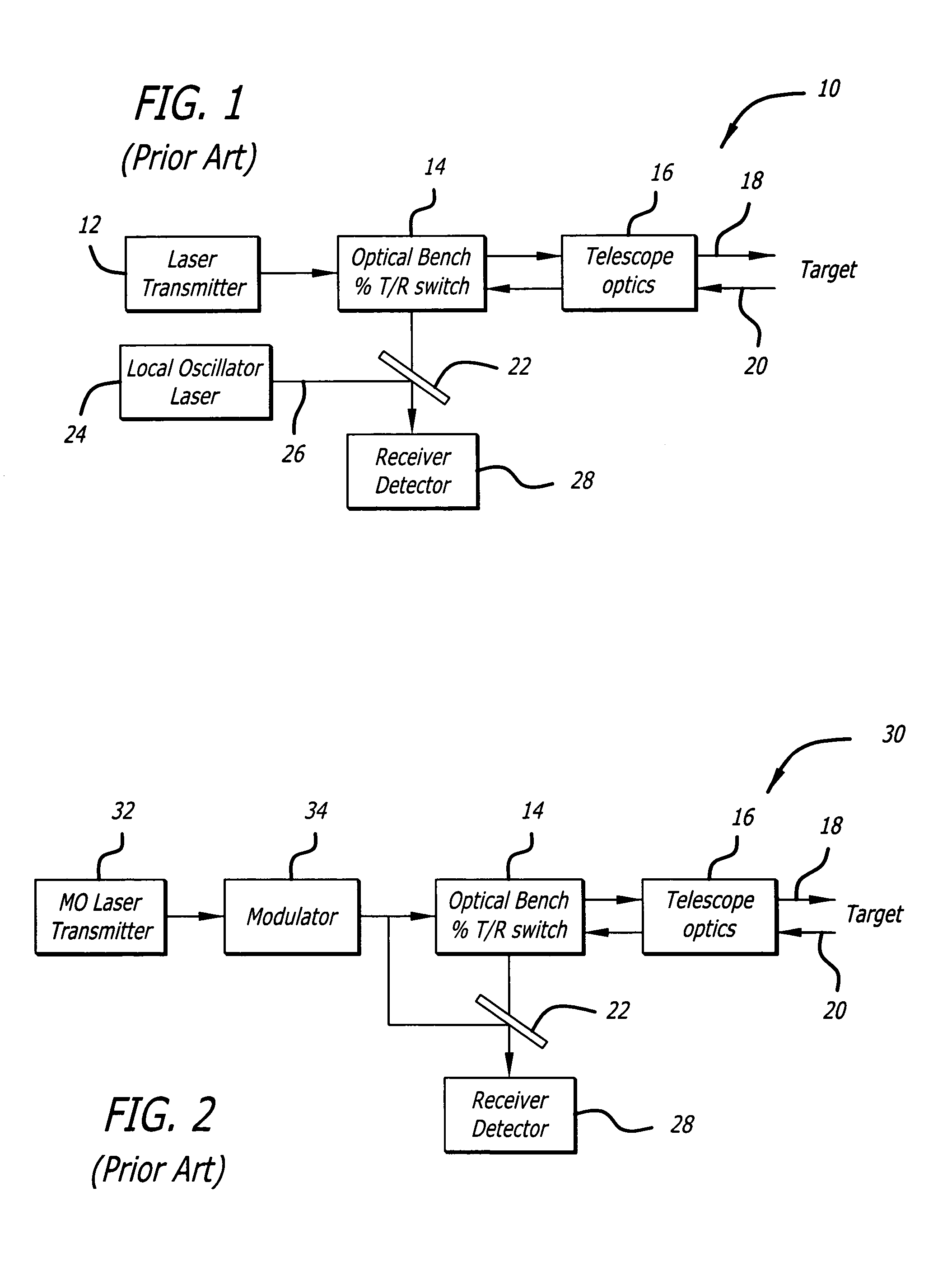
[0017]FIG. 1 is a simplified block diagram of a conventional coherent ladar system 10 employing heterodyne detection. The ladar system 10 includes a laser transmitter 12 that generates a laser signal, and an optical bench 14 adapted to direct the laser signal to telescope optics 16, which transmit the laser signal 18 towards a target and receive a la...


PUM


Abstract

A ladar system with phase correction. The novel ladar system includes optics for receiving a first signal that is a reflected version of a transmitted laser signal, an optical delay line for providing a second signal that is a delayed version of the transmitted laser signal, and a mechanism for mixing the first signal with the second signal. The second signal is delayed by a time TD that reduces a relative time difference between the first and second signals such that phase errors caused by laser transmitter instabilities and nonlinear modulation are less than a predetermined level.

Description

BACKGROUND OF THE INVENTION[0001]1. Field of the Invention[0002]The present invention relates to ladar systems. More specifically, the present invention relates to systems and methods for correcting phase errors in coherent ladar systems.[0003]2. Description of the Related Art[0004]Coherent ladar applications and techniques are beginning to be considered for various applications including commercial and military. These include high resolution velocity measurements, remote vibration measurements, optical synthetic aperture implementations, and others. High resolution coherent ladars typically require very stable laser oscillators and well controlled modulation waveforms. However, the increasing demand for fidelity, resolution, and long range of operation make the component requirements impossible to meet using conventional ladar systems.[0005]A ladar system typically includes a laser transmitter that produces a laser signal which is transmitted towards a target scene. The laser signa...

Claims


Application Information

Patent Timeline
Patent Type & Authority Patents(United States)
IPC IPC(8): G01C3/08G01S17/34
CPCG01S7/497G01S17/325G01S17/34
Inventor HALMOS, MAURICE J.KLOTZ, MATTHEW J.BULOT, JEAN-PAUL
Owner RAYTHEON CO
Why Eureka
Try Eureka