Manipulation device for wheelchair footrests

a technology of manipulation device and footrest, which is applied in the field of manipulation device for wheelchair footrest, can solve the problems of pain to the pain of the user or helper, and the difficulty of direct and manual or kicking operation to open or close the footrest, so as to achieve convenient mounting, simple structure, and easy operation. and safety

Inactive Publication Date: 2008-03-25
KOUJI FUJIHARA
View PDF10 Cites 10 Cited by
  • Summary
  • Abstract
  • Description
  • Claims
  • Application Information

AI Technical Summary

Benefits of technology

[0012]It also is to be noted that the manual lever would be operated erroneously and immoderately by the user having his or her feet rested on the foot plates. In such an event, the resilient tube absorbs an extraordinary tension due to its yielding elongation, so as to protect the device from any forcible stress. Even if the user lifted his or her feet off the foot plates, the resilient tube would shrink gently not to cause them to leap up.
[0002]Some wheelchair footrests of the types known in the art comprise a pair of shafts extending forwards from lateral sides of a main frame, and a pair of foot plates pivoted to the shafts. The foot plates are allowed to swivel between their horizontal (closed) positions facing close to each other and their upright idle (open) positions. However, a retention mechanism will prevent each foot plate from any unintentional fall from its open upright position to closed horizontal position. Such a mechanism usually comprises a spring, threaded members and / or the like intervening between the pivoting portions of foot plate and shaft, thereby imparting thereto a strong frictional resistance.
[0014]As summarized above, the manipulation device now provided for the footrests is simple in structure, and its operation is easier and safer even if it is readily mounted on any existing wheelchairs currently available on the market. This device is not only of a simplified structure but also has such an open mechanical feature as facilitating access thereto for the purpose of cleaning and sterilization.
[0015]Where the user or helper wants to alter the height of foot plates, he or she just has to change the exposed length of the wire protruding out of the tube. Such an adjustment of the actuating means enables its constituent parts, that is the wire and the tube, to be always aligned generally straight without any excessive slackness. The actuating means has no fear of getting in the way or catching any obstacle, thus obviating any accidents that would be caused by a slack wire.
[0012]It also is to be noted that the manual lever would be operated erroneously and immoderately by the user having his or her feet rested on the foot plates. In such an event, the resilient tube absorbs an extraordinary tension due to its yielding elongation, so as to protect the device from any forcible stress. Even if the user lifted his or her feet off the foot plates, the resilient tube would shrink gently not to cause them to leap up.

Problems solved by technology

Usually, such a direct and manual or kicking operation to open or close the foot plates is not so easy to the user or helper.
In particular, if the user sitting on the wheelchair is a handicapped or aged person, it may be considerably difficult to bend his or her body forwards and deeply to handle the foot plates.
This causes a pain to him or her, and a narrow forward space will make the operation very difficult.
Further, bare hands of the user or helper touching the foot plates will catch an amount of dirt and a number of bacteria that souls of his or her shoes have picked up and collected from streets, hospital floors or lavatories.
This is a hygienic problem that may spread any infectious diseases in hospitals, so that the wheelchair of the described types have been washed and sterilized periodically.
The wheelchair described in Patent Reference 1 is somewhat complicated in structure due to the urging means such as coiled springs for always biasing upwards the foot plates towards their upright open (idle) position.
Besides, it would be difficult to wash out dust and bacteria that have migrated from the foot plates to the urging means.
Wrong operation of the manual levers may possibly cause the urged foot plates to leap up to the upright open (idle) position, thus bring about some difficulty in use.
Therefore, it any foreign matter caught the slack wires, the manual levers would make a malfunction.
However, it had not suggested any details with respect to structure of an actuating means for connecting each foot plate to a manual lever.

Method used


Image

  • Manipulation device for wheelchair footrests
  • Manipulation device for wheelchair footrests
  • Manipulation device for wheelchair footrests

Examples


Embodiment Construction

[0029]Now some embodiments of the present invention will be described referring to the accompanying drawings.

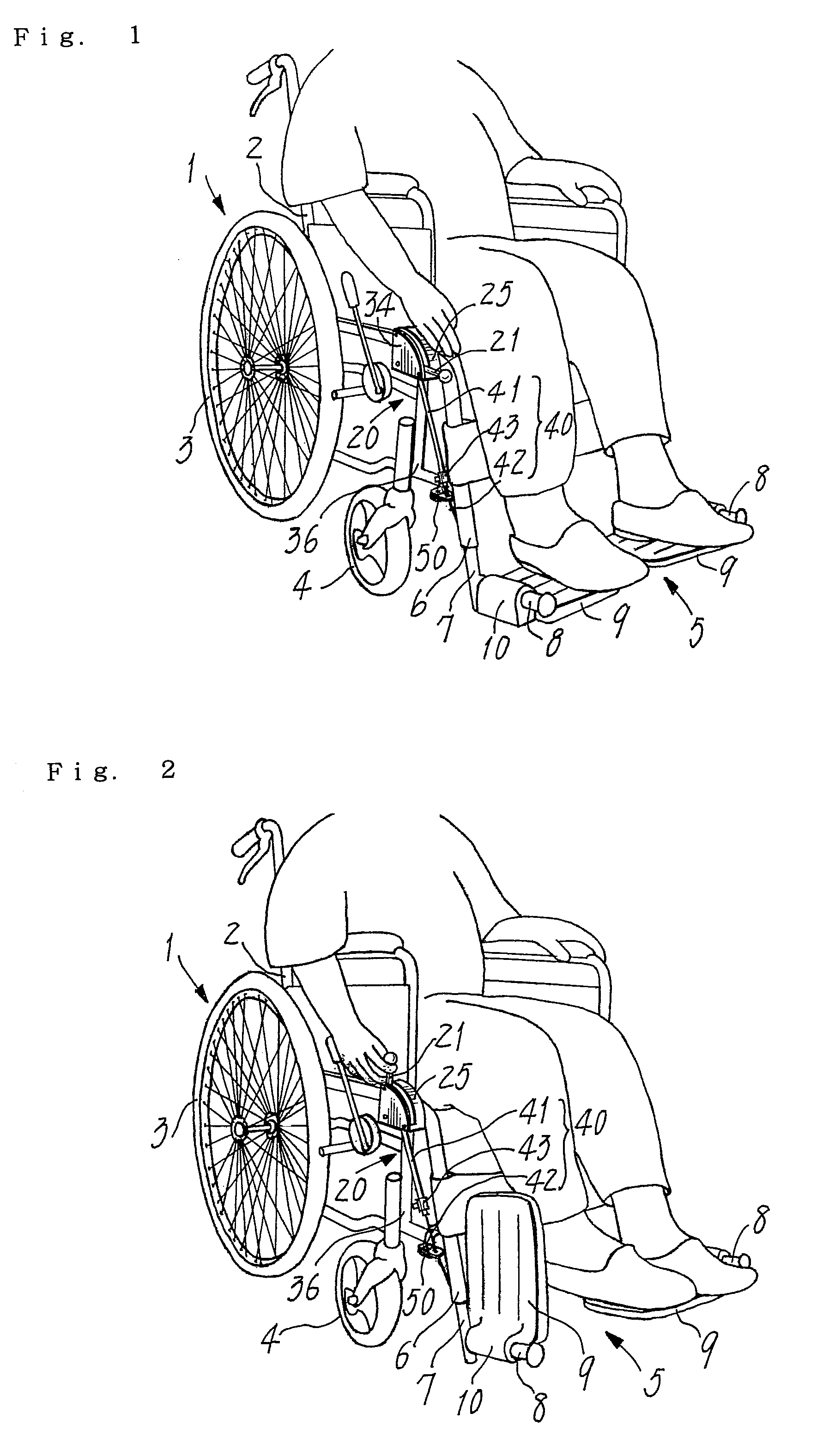
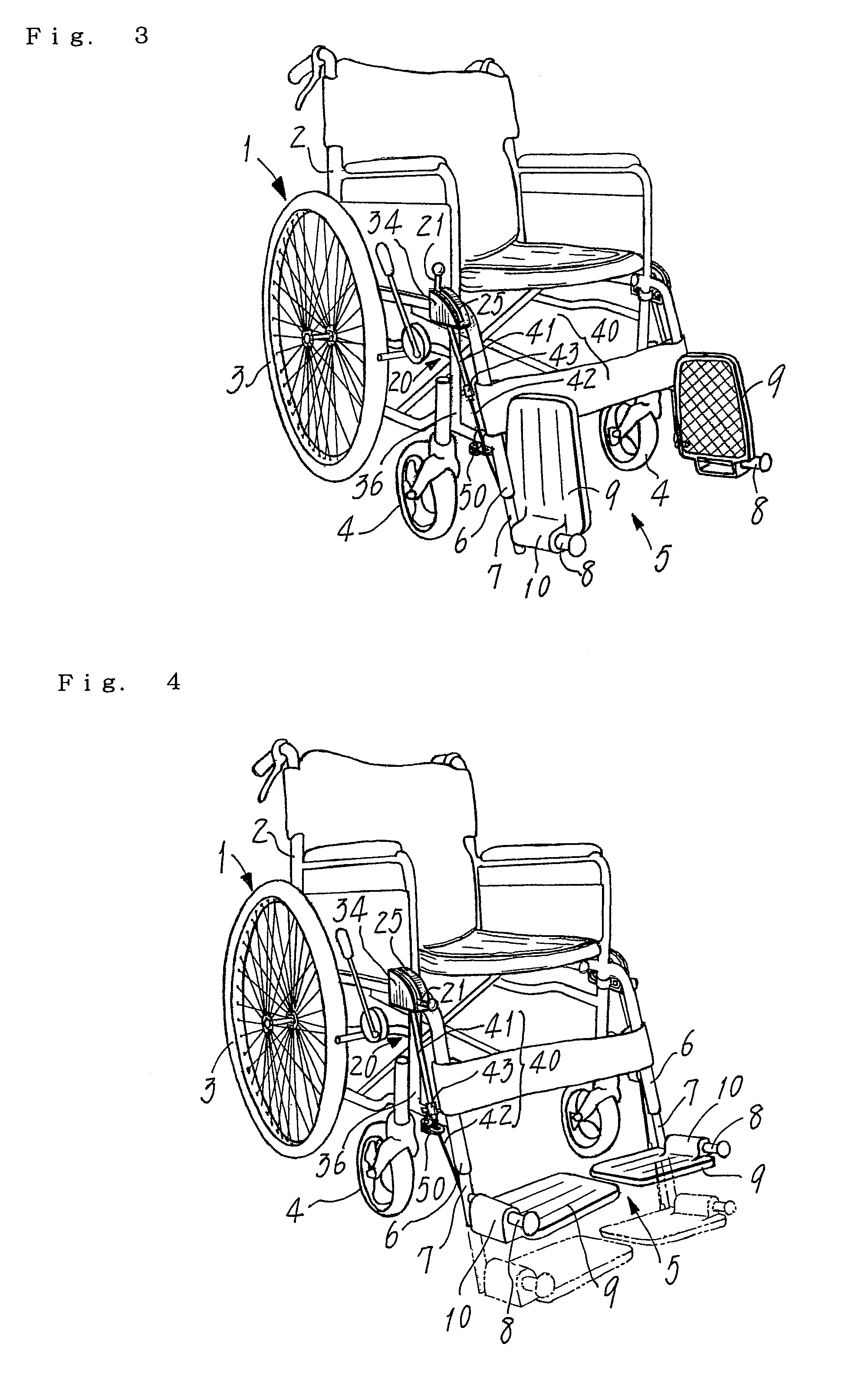
[0030]FIGS. 1 and 2 show a wheelchair 1 provided with a manipulation device that is constructed herein for footrests each comprising a foot plate. Except for the manipulation device, this wheelchair 1 is of the same structure in its entirety as those of some types now available on the market. Therefore, only an outline of the wheelchair will be given here. A main frame 2 is generally composed of some lengths of metal pipes, and attached to this frame are a pair of large-diameter rear wheels 3 and a pair of small-diameter front wheels 4. Footrests 5 are disposed at a frontal end region of the main frame 2.

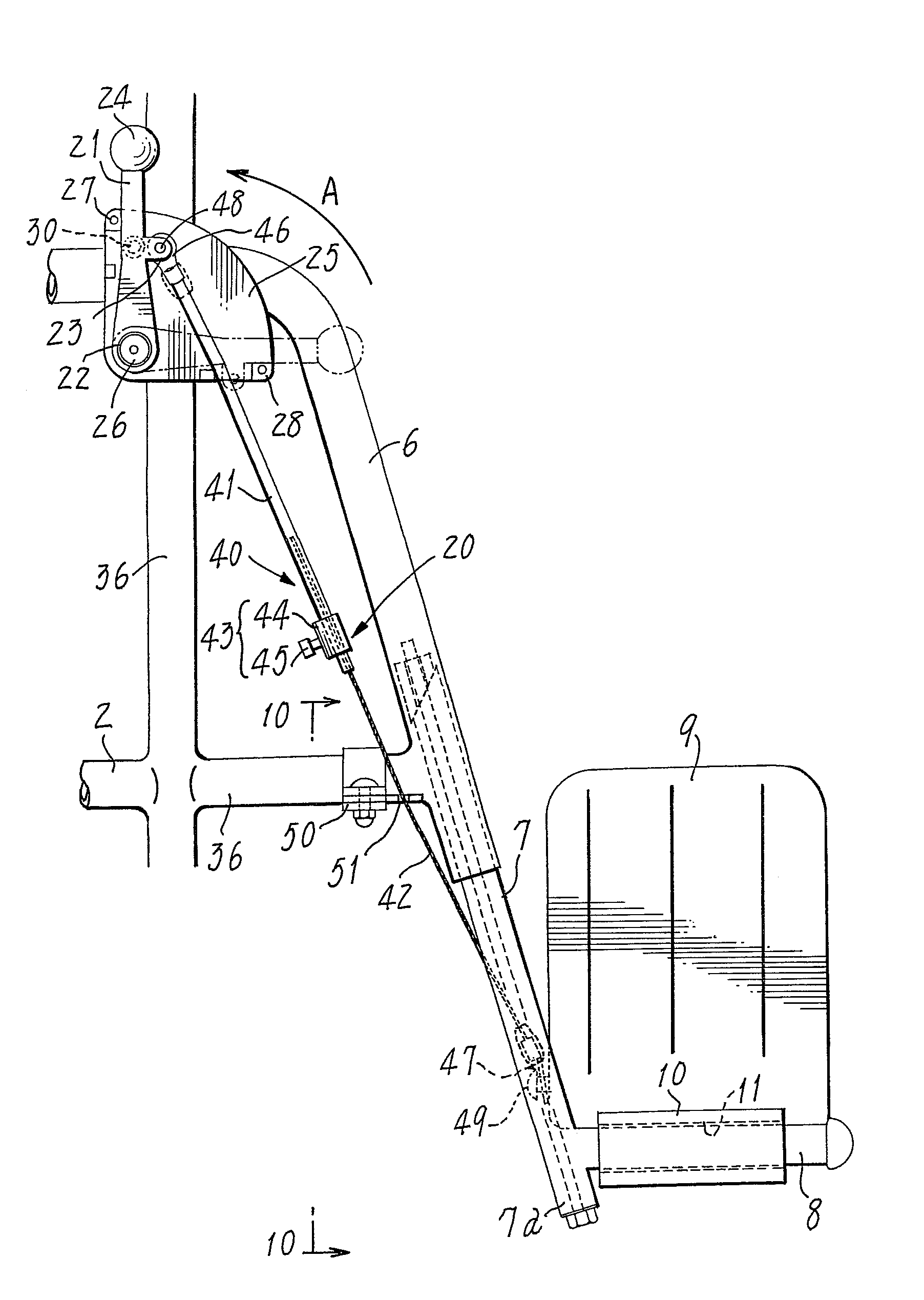
[0031]Each footrest 5 comprises a lift pipe 7 held in place by a support pipe 6 that extends forwards from a front region of the main frame 2. The lift pipe 7 is capable of taking any desired vertical position relative to the support pipe 6. A pair of longitudinal shafts 8 pr...


PUM


Abstract

A manipulation device is for wheelchair footrests that have a pair of shafts (8) extending forwards from opposite forward sides of the main frame (2) and a pair of foot plates (9) pivoted at lateral portions to the shafts. This device has manual levers (21) at the forward sides and actuating means (40) that connects the levers (21) to foot plates (9) and consists of a resilient tube (41), a metal wire (42) and a setting retainer (43) for securing the tube to the wire. The tube (41) can elongate in response to an extraordinary tension exceeding a normal stress imparted to said tube, and the wire (42) loosely inserted in the tube (41) can alter an exposed length. An end of each wire (42) is connected to the foot plate (9) at its rear portion located near the shaft (8) pivoting the foot plate. An end of each tube (41) is connected to the manual lever (21) operating to pull up the tube (41) with the wire (42) such that the foot plate (9) rotates and rises to the upright idle position.

Description

FIELD OF THE INVENTION[0001]The present invention relates to such a manipulation device for wheel-chair footrests that foot plates thereof supporting the feet of a user of this wheelchair are capable of being operated.BACKGROUND ART[0002]Some wheelchair footrests of the types known in the art comprise a pair of shafts extending forwards from lateral sides of a main frame, and a pair of foot plates pivoted to the shafts. The foot plates are allowed to swivel between their horizontal (closed) positions facing close to each other and their upright idle (open) positions. However, a retention mechanism will prevent each foot plate from any unintentional fall from its open upright position to closed horizontal position. Such a mechanism usually comprises a spring, threaded members and / or the like intervening between the pivoting portions of foot plate and shaft, thereby imparting thereto a strong frictional resistance.[0003]In use, whenever getting on or off the wheelchair, every handicap...

Claims


Application Information

Patent Timeline
Patent Type & Authority Patents(United States)
IPC IPC(8): A61G5/02
CPCA61G5/12A61G2005/1054A61G2005/128A61G5/1054A61G5/128A61G5/10
Inventor FUJIHARA, KOUJIFUJIHARA, TAKAAKI
Owner KOUJI FUJIHARA
Why Eureka
Try Eureka