Radome for vehicles

a technology of radome and vehicle, applied in the direction of antenna details, coatings, antennas, etc., can solve the problems of reducing the appearance of the front grille of the radar window, affecting the high gloss reflectivity of the protection hard coat, and unsightly internal parts of the vehicle, so as to reduce the disturbance of the introduction, improve the visual perception of all decorative details, and reduce the effect of optical reflection

Active Publication Date: 2019-01-10
ZANINI AUTO GRUP
View PDF3 Cites 3 Cited by
  • Summary
  • Abstract
  • Description
  • Claims
  • Application Information

AI Technical Summary

Benefits of technology

[0023]A liquid hard coat layer is applied on top of the overlying radio transmissive resin to protect the substrate material from mechanical, chemical or radiation stresses. This varnish gives a very glossy shade on the surface pointing outwards from the vehicle, which causes some optical disturbances and does not permit clear observation of the metallic decoration behind.
[0024]To diminish the disturbances introduced by the hard coat layer, an anti-reflecting layer will be added on top of the hard coat layer to decrease the optical reflections at the air interface and improve the visual perception of all decorative details contained below, no matter which ambient conditions the object is in. This layer will be chosen to have excellent adhesion properties with the hard coat, otherwise the durability of the visual improvement could be severely constrained. Thus, depending on the resin material selected to cover the radome substrate and its decoration layer, the hard coat will be selected afterwards, and the same will be done finally with the anti-reflection layer.
[0026]With the radome according to the present invention, the anti-reflection layer will eliminate the high reflecting disturbances introduced by the top coat, which will significantly improve radome aesthetics.

Problems solved by technology

However, the radar window diminished the appearance of the front grill due to the interruption of the pattern of the grill structural elements.
Further, unsightly internal portions of the vehicle, like the radar transmitter-receiver, could be seen through the radar window.
A limitation takes place regarding high gloss reflectivity of the protection hard coat applied on top of the overlying radio transmissive resin.
This impedes to clearly distinguish any pattern drawings, logos or any other image design contained on the substrate described in WO2012066417A1.
This method is limited performance-wise, and so the successive deposition of several layers is preferred as anti-reflection coating.
However, the method in U.S. Pat. No. 4,929,278 leads to unacceptable curing times if an industrialized in-line production is required, because the time in stock of the samples would lead to a large product cost increase.
To achieve these properties, successive depositions take place, and the process becomes complex and costly.

Method used


Image

  • Radome for vehicles
  • Radome for vehicles
  • Radome for vehicles

Examples


examples

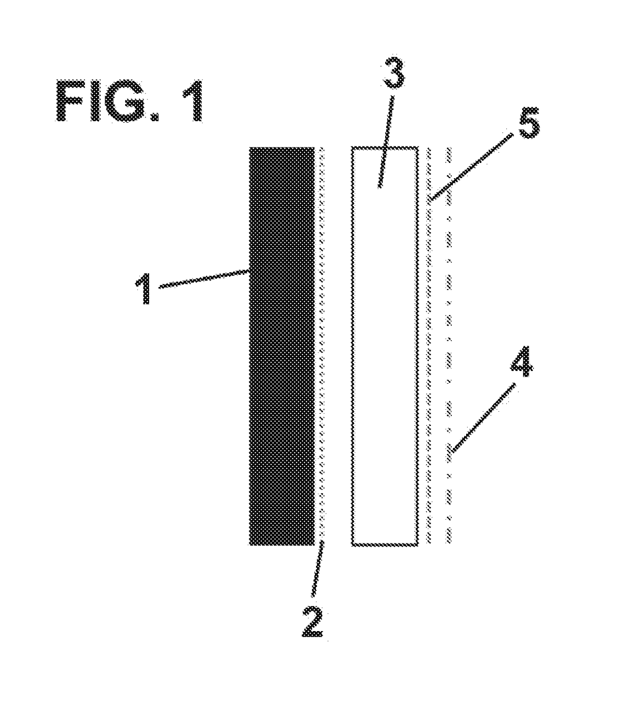
[0048]In the first example shown in FIG. 1, the radome 10 according to the present invention comprises, shown in order from the distal to the proximal side of the radome:

[0049]1—base layer made from a radio transmissive resin, base layer;

[0050]2—bright decoration layer comprising one or more metalloids, or one or more metalloids and one or more oxides on the proximal face;

[0051]3—transparent resin layer made from a radio transmissive layer abutting the decoration layer;

[0052]5—hard coat on proximal face;

[0053]4'anti-reflective coating comprising successive layers of titanium dioxide and germanium dioxide on proximal face.

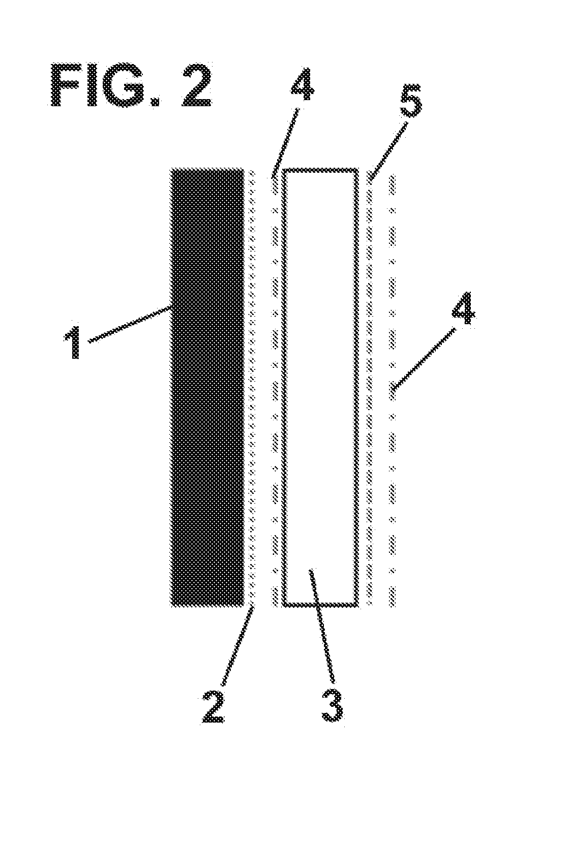
[0054]In the second example shown in FIG. 2, the radome 10 according to the present invention comprises, shown in order from the distal to the proximal side of the radome:

[0055]1—base layer made from radio transmissive resin;

[0056]2—bright decoration layer comprising one or more metalloids, or one or more metalloids and one or more oxides on proximal face;

[0057]3—tr...


PUM

PropertyMeasurementUnit
melting pointaaaaaaaaaa
transparentaaaaaaaaaa
gloss reflectivityaaaaaaaaaa

Abstract

A radome (10) for vehicles defining a proximal side and a distal side, comprising a base layer (1) formed of a radio transmissive resin, the base layer (1) defining a proximal face and a distal face; a decoration layer (2) applied to the proximal face of the base layer (1), the decoration layer (2) comprising a metalloid or a metalloid alloy; characterized in that the radome (10) also comprises an anti-reflective coating (4) placed proximal with respect to the decoration layer (2).The anti-reflection layer will eliminate the high reflecting disturbances introduced by the top coat, which will significantly improve radome aesthetics.

Description

RELATED APPLICATION[0001]This application claims the benefit of priority of European Patent Application No. 17382436.8 filed Jul. 5, 2017, the contents of which are incorporated herein by reference in their entirety.FIELD AND BACKGROUND OF THE INVENTION[0002]The present invention refers to a radome for protecting a radar device while presenting an outstanding aesthetical appearance, especially for radar devices disposed behind the front grill of an automobile.[0003]In general, radio transmitter-receiver devices, such as a millimeter-wave radar, have been employed as sensors for vehicular collision avoidance and adaptive cruise control systems.[0004]In a radar system or the like that measures obstacles in front of an automobile and the distance between automobiles, the antenna was preferably positioned in the center at the front of the vehicle to obtain maximum performance. Although the radar antenna could be installed near the front grill of automobile, it was preferable to conceal ...

Claims


Application Information

Patent Timeline
Patent Type & Authority Applications(United States)
IPC IPC(8): H01Q1/42G02B1/11
CPCG02B1/11H01Q1/42H01Q1/3233H01Q1/422
Inventor MAYER PUJADAS, AUGUSTOJAIR PERALTA, JERSONARMENGOL ROCASPANA, JOSEP MARIA
Owner ZANINI AUTO GRUP
Why Eureka
Try Eureka