Semi-passive radio frequency identification (RFID) tag with active beacon

a radio frequency identification and passive technology, applied in the field of semi-passive radio frequency identification (rfid) tags with active beacons, radio frequency identification devices, etc., can solve problems such as insufficient range for some applications

Active Publication Date: 2008-03-25
BATTELLE MEMORIAL INST
View PDF41 Cites 943 Cited by
  • Summary
  • Abstract
  • Description
  • Claims
  • Application Information

AI Technical Summary

Problems solved by technology

While this is successful for tags that are located in close proximity to an interrogator, for example less than three meters, this may be insufficient range for some applications, for example greater than 100 meters.

Method used


Image

  • Semi-passive radio frequency identification (RFID) tag with active beacon
  • Semi-passive radio frequency identification (RFID) tag with active beacon
  • Semi-passive radio frequency identification (RFID) tag with active beacon

Examples


Embodiment Construction

[0019]Attention is directed to the following commonly assigned applications, which are incorporated herein by reference:

[0020]U.S. patent application Ser. No. 10 / 263,826, filed Oct. 2, 2002, entitled “Radio Frequency Identification Device Communications Systems, Wireless Communication Devices, Backscatter Communication Methods and Radio Frequency Identification Device Communication Methods,” by inventors Mike A. Hughes and Richard M. Pratt; U.S. patent application Ser. No. 10 / 263,809, filed Oct. 2, 2002, entitled “Method of Simultaneously Reading Multiple Radio Frequency Tags, RF Tag, and RF Reader,” by inventors Emre Ertin, Richard M. Pratt, Mike A. Hughes, Kevin L. Priddy, and Wayne M. Lechelt; U.S. patent application Ser. No. 10 / 263,873, filed Oct. 2, 2002, entitled “RFID System and Method Including Tag ID Compression,” by inventors Richard M. Pratt and Mike A. Hughes; U.S. patent application Ser. No. 10 / 264,078, filed Oct. 2, 2002, entitled “System and Method to Identify Multipl...


PUM


Abstract

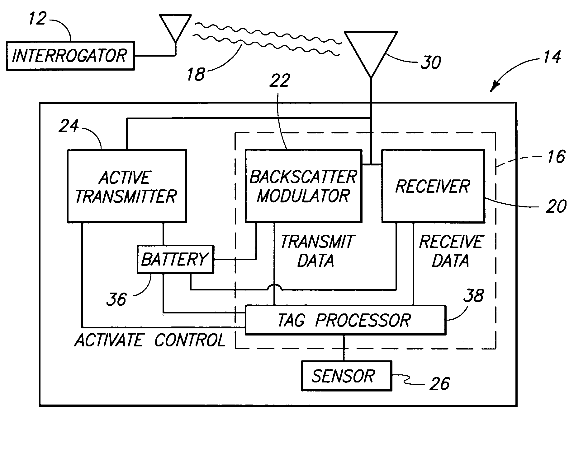
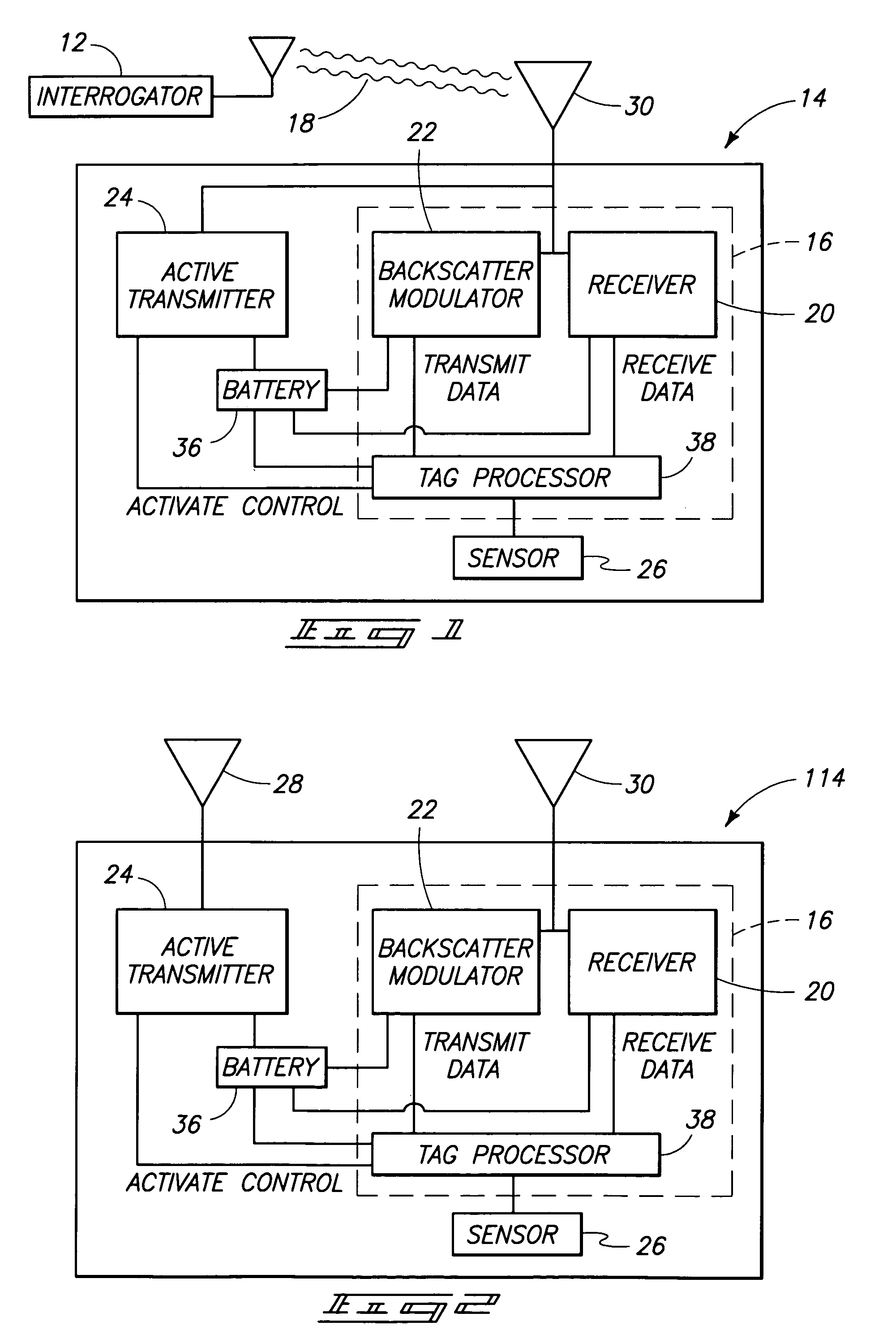
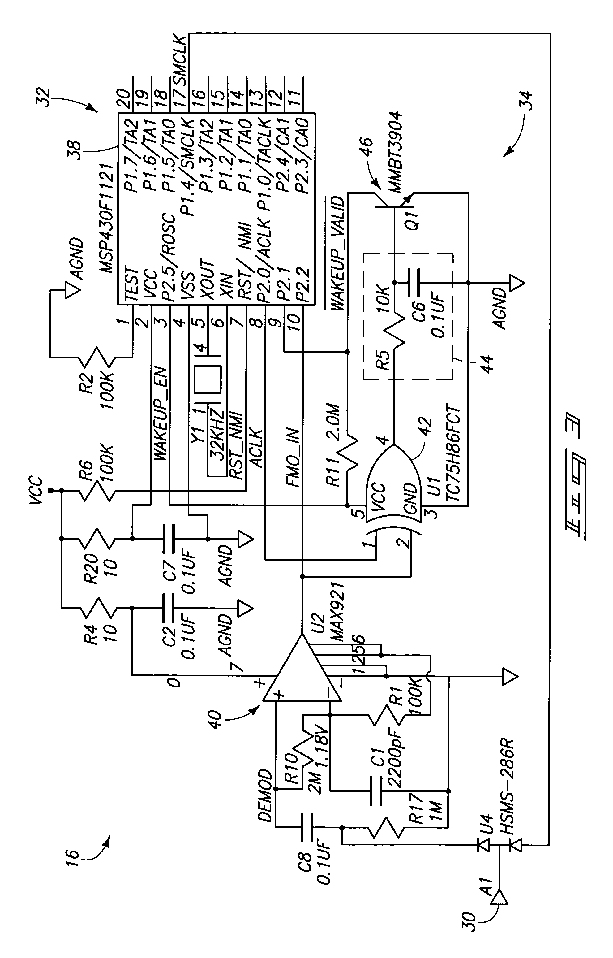
A radio frequency beacon device for use with a backscatter interrogator includes a processor; a receiver coupled to the processor; a backscatter modulator coupled to the processor; and an active transmitter coupled to the processor, the active transmitter being configured to transmit an RF signal, in response to a trigger signal, regardless of whether the interrogator is providing a carrier wave for backscatter modulation by the backscatter modulator. Other methods and apparatus are provided.

Description

TECHNICAL FIELD[0001]The invention relates to radio frequency communications devices and methods. Other aspects of the invention relate to radio frequency identification devices.BACKGROUND OF THE INVENTION[0002]Remote communication utilizing wireless equipment typically relies on radio frequency (RF) technology, which is employed in many industries. One application of RF technology is in locating, identifying, and tracking objects, such as animals, inventory, and vehicles.[0003]RF identification (RFID) tag systems have been developed to identify, monitor, or control remote objects.[0004]An advantage of RFID systems is the non-contact, non-line-of-sight capability of the technology. Tags can be read through a variety of substances such as snow, fog, ice, paint, dirt, and other visually and environmentally challenging conditions where bar codes or other optically-read technologies would be useless. RF tags can also be read at remarkable speeds, in most cases responding in less than 10...

Claims


Application Information

Patent Timeline
Patent Type & Authority Patents(United States)
IPC IPC(8): H04Q5/22G08B13/14G06K19/07
CPCG06K19/0717G06K19/0723G06K19/07786
Inventor HUGHES, MICHAEL A.PRATT, RICHARD M.
Owner BATTELLE MEMORIAL INST
Why Eureka
Try Eureka