

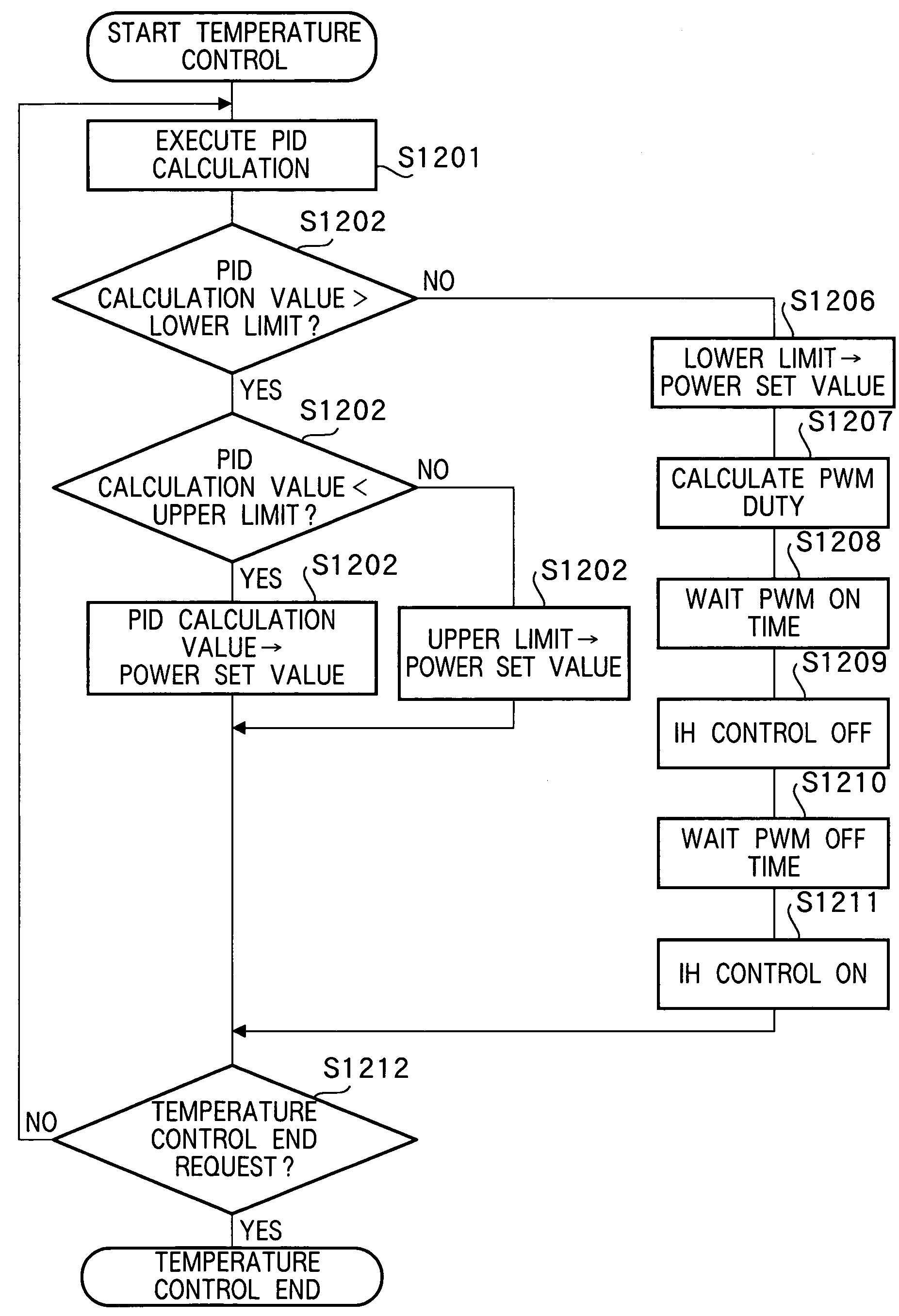
Image heating apparatus including PID control
a heating apparatus and image technology, applied in the field of image heating apparatus, can solve the problems of increasing the temperature of the image heating body, excessive overshooting, and increasing the overshooting, and achieve the effect of reducing the overshooting
- Summary
- Abstract
- Description
- Claims
- Application Information
AI Technical Summary
Benefits of technology
Problems solved by technology
Method used
Image

Examples
embodiment 1
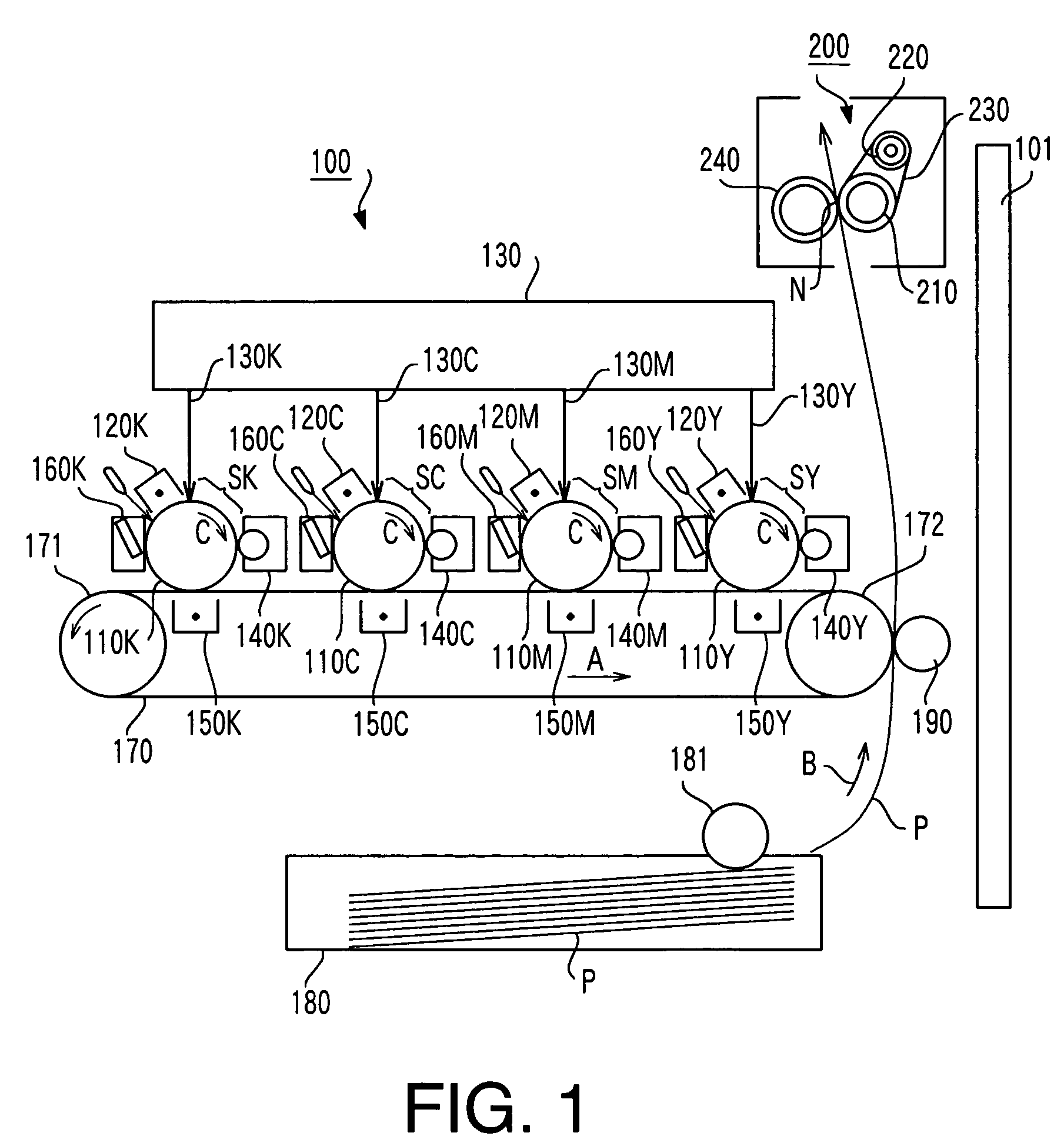
[0049]FIG. 1 is a schematic cross-sectional view of an image formation apparatus mounted with a fixing apparatus using an image heating apparatus according to Embodiment 1 of the present invention as an image heat generation section. This image formation apparatus 100 is a tandem-scheme image formation apparatus. In the image formation apparatus 100, toner images of four colors contributing to the coloring of a color image are individually formed on four image carriers, primary-transferred onto an intermediate transfer body overlapped on one another sequentially and then these primary transfer images are collectively transferred (secondary transfer) to a recording medium.
[0050]It goes without saying that the image heating apparatus according to this Embodiment 1 is not limited to only the tandem-scheme image formation apparatus, but can be mounted on all types of image formation apparatus.
[0051]In FIG. 1, suffixes Y, M, C, K of reference numerals assigned the respective components o...
embodiment 2
[0254]Next, an image heating apparatus according to Embodiment 2 of the present invention will be explained.
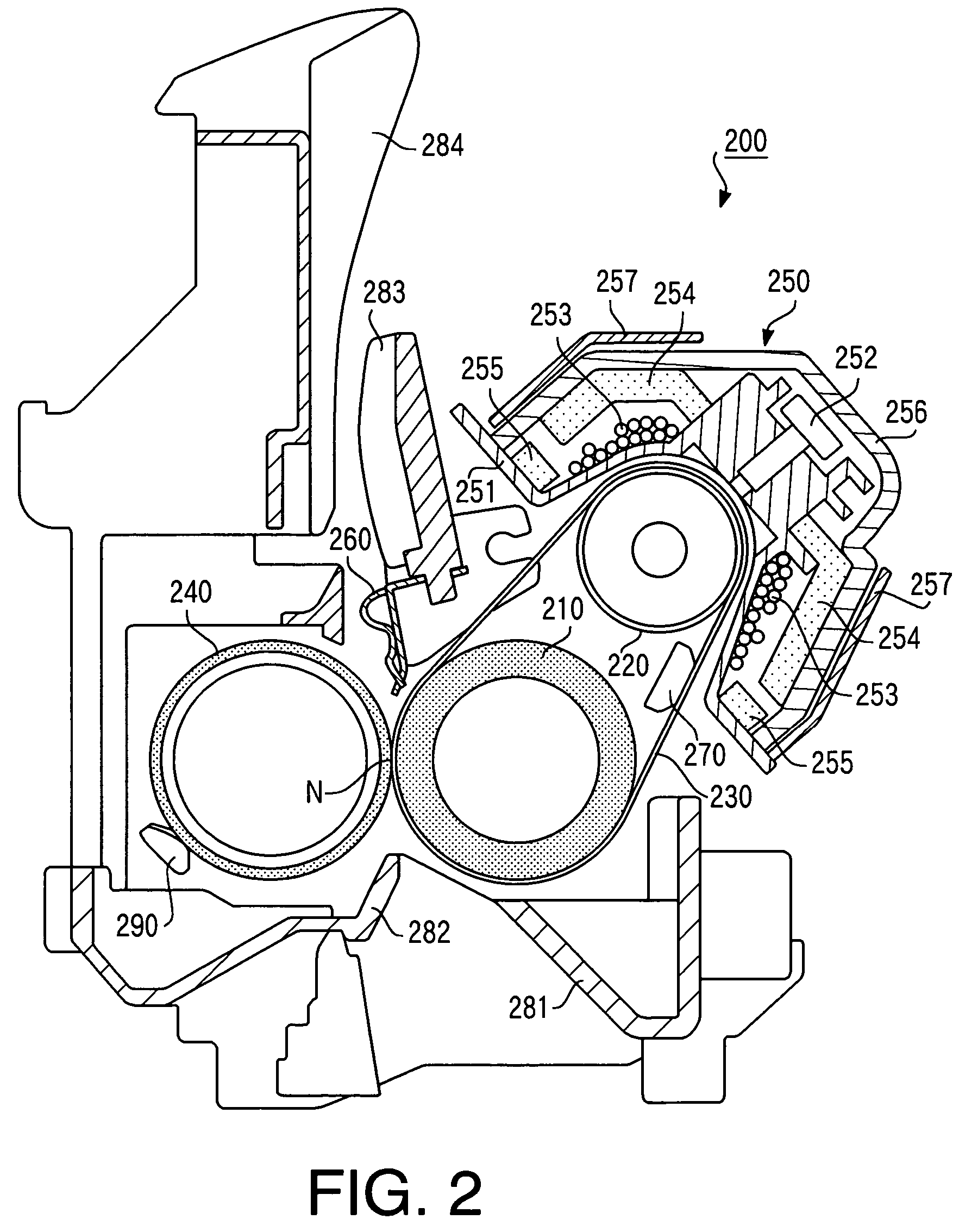
[0255]The fixing belt 230 of the fixing apparatus 200 has a smaller heat capacity and quicker temperature drop. For this reason, when the first page is printed after the power to the image formation apparatus 100 is turned ON, as shown, for example, in FIG. 17, the ambient temperature of the fixing apparatus 200 at time a is low, but the temperature of the fixing belt 230 is high because it is immediately after the printing.
[0256]On the other hand, when printing by the image formation apparatus 100 is carried out consecutively or intermittently, as shown in FIG. 18, the temperature of the fixing belt 230 and ambient temperature of the fixing apparatus 200 are high at a time b, and the temperature of the pressurizing roller 240 is also high.
[0257]Therefore, in order to keep the temperature of the fixing belt 230 to an image fixing temperature appropriate for heating and fixing ...
embodiment 3
[0262]Next, an image heating apparatus according to Embodiment 3 of the present invention will be explained.
[0263]The temperature of the pressurizing roller 240 of the fixing apparatus 200 increases gradually with serial printing when serial printing is performed from a low-temperature state, but as shown in FIG. 19, saturation occurs at a pressurizing roller saturation temperature around, for example, 90° C. In this case, the ambient temperature of the fixing apparatus 200 is close to the temperature of the pressurizing roller 240.
[0264]In contrast, when serial printing is performed when the temperature of the pressurizing roller 240 is high due to intermittent printing, etc., the pressurizing roller 240 is deprived of heat when recording paper P passes through, and the temperature of the pressurizing roller 240 decreases gradually as shown in FIG. 20 and almost stabilizes at a pressurizing roller saturation temperature, for example, between 80° C. and 90° C.
[0265]For this reason, ...
PUM
 Abstract
Description
Claims
Application Information