Vehicle-behavior detecting apparatus and vehicle-behavior controlling apparatus

a technology of vehicle behavior and detecting apparatus, which is applied in the direction of underwater vessels, non-deflectable wheel steering, brake components, etc., can solve the problems of vehicle understeer, vehicle load shifting backward, and increased vertical load on the rear wheels, so as to reduce the control delay, improve the turning performance, and increase the critical lateral acceleration

Inactive Publication Date: 2008-03-25
SUBARU CORP
View PDF5 Cites 5 Cited by
  • Summary
  • Abstract
  • Description
  • Claims
  • Application Information

AI Technical Summary

Benefits of technology

[0010]It is an object of the present invention to provide a vehicle-behavior detecting apparatus and a vehicle-behavior controlling apparatus which instantly detect a variation in the vehicle behavior during turning, thereby reducing a control delay; increase the critical lateral acceleration during accelerated turning, thereby improving a turning performance; and provide an excellent running stability during decelerated turning.

Problems solved by technology

When a driver suddenly presses down on an accelerator pedal to accelerate the vehicle, however, the vehicle load shifts backward, and a vertical load on rear wheels increases.
Therefore, the vehicle exhibits an understeer.
Therefore, the vehicle exhibits an oversteer.
Such an understeer or oversteer caused by operation of the accelerator pedal or the brake pedal destabilizes a posture of the vehicle.
Since the amount to be controlled is determined after the actual yaw rate is detected, the control tends to be late.
In addition, since the vehicle behavior is controlled by applying the braking force to a particular wheel, torque loss is large, and excellent acceleration performance cannot be obtained.
Furthermore, since the vehicle-behavior control during turning is delayed, there are problems in that a critical lateral acceleration cannot be increased during accelerated turning, and a running stability is impaired during decelerated turning.

Method used


Image

  • Vehicle-behavior detecting apparatus and vehicle-behavior controlling apparatus
  • Vehicle-behavior detecting apparatus and vehicle-behavior controlling apparatus
  • Vehicle-behavior detecting apparatus and vehicle-behavior controlling apparatus

Examples


Embodiment Construction

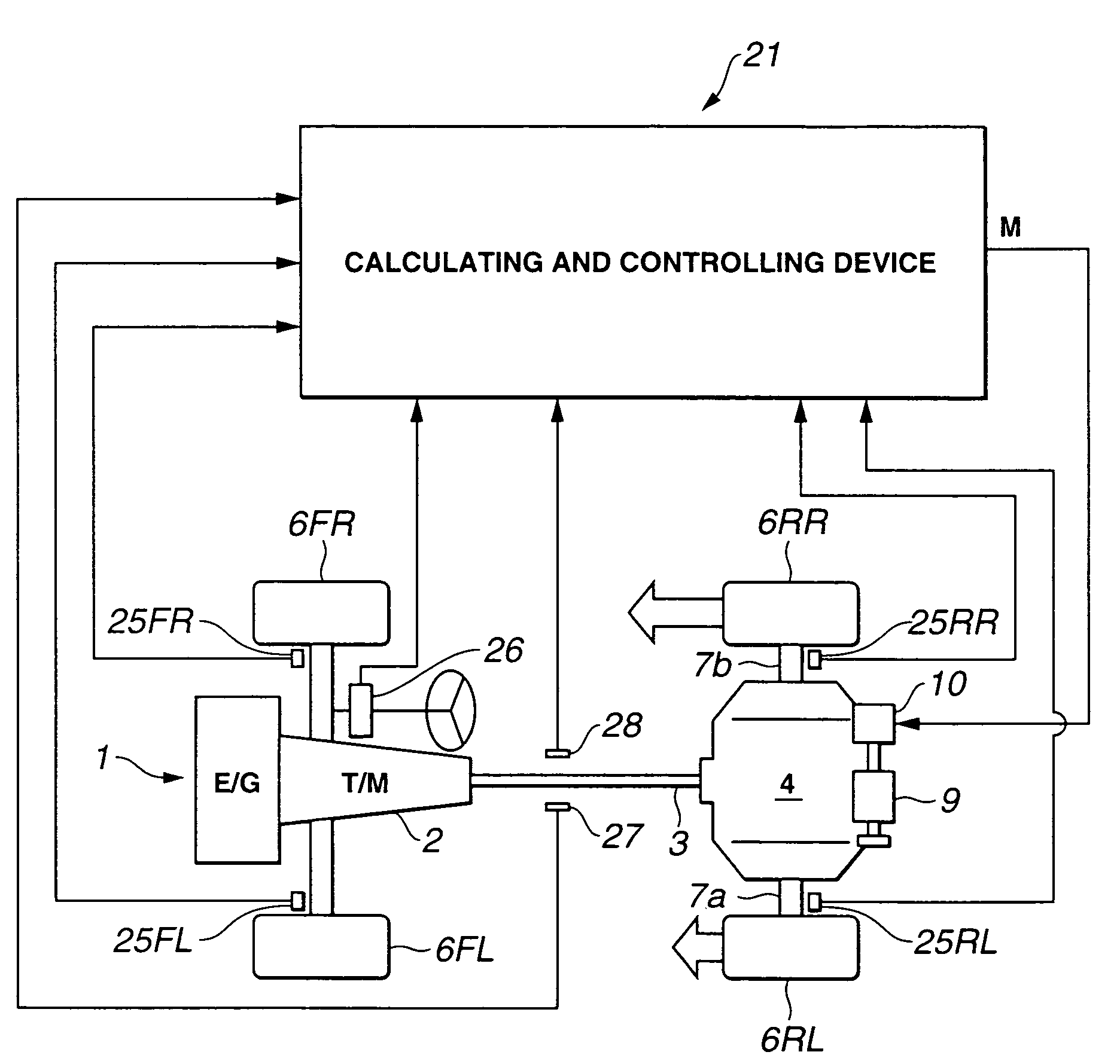
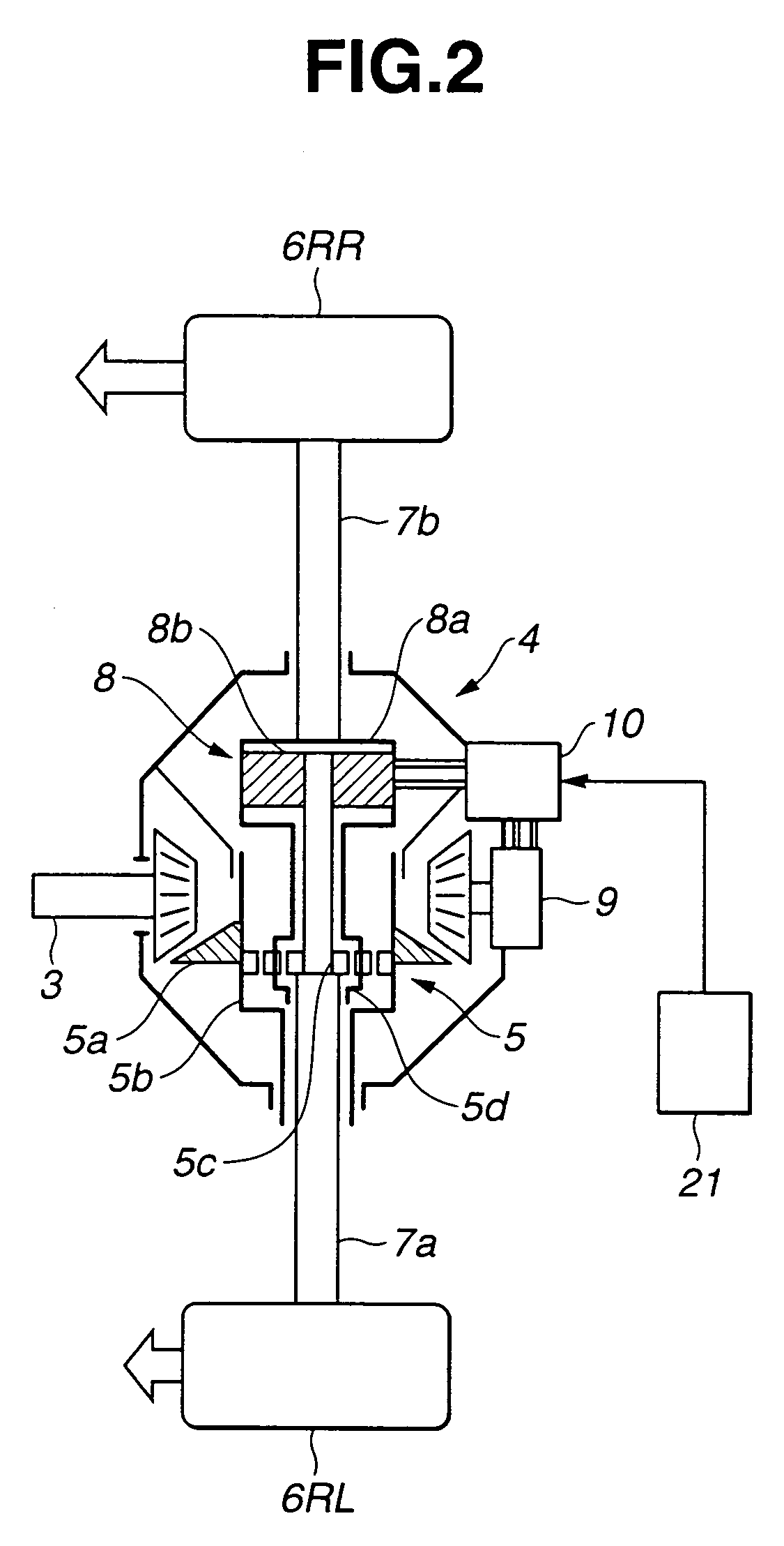
[0019]In FIG. 1, a power from an engine 1 is transmitted to a rear left wheel 6RL and a rear right wheel 6RR via a transmission 2, a propeller shaft 3, and a driving-force distribution device 4. The device 4 controls a vehicle behavior by varying a driving-force distribution between the rear left wheel 6RL and the rear right wheel 6RR according to the vehicle behavior during turning. In a case where drive wheels are a front left wheel 6FL and a front right wheel 6FR, the driving-force distribution device 4 is provided for the front wheels.

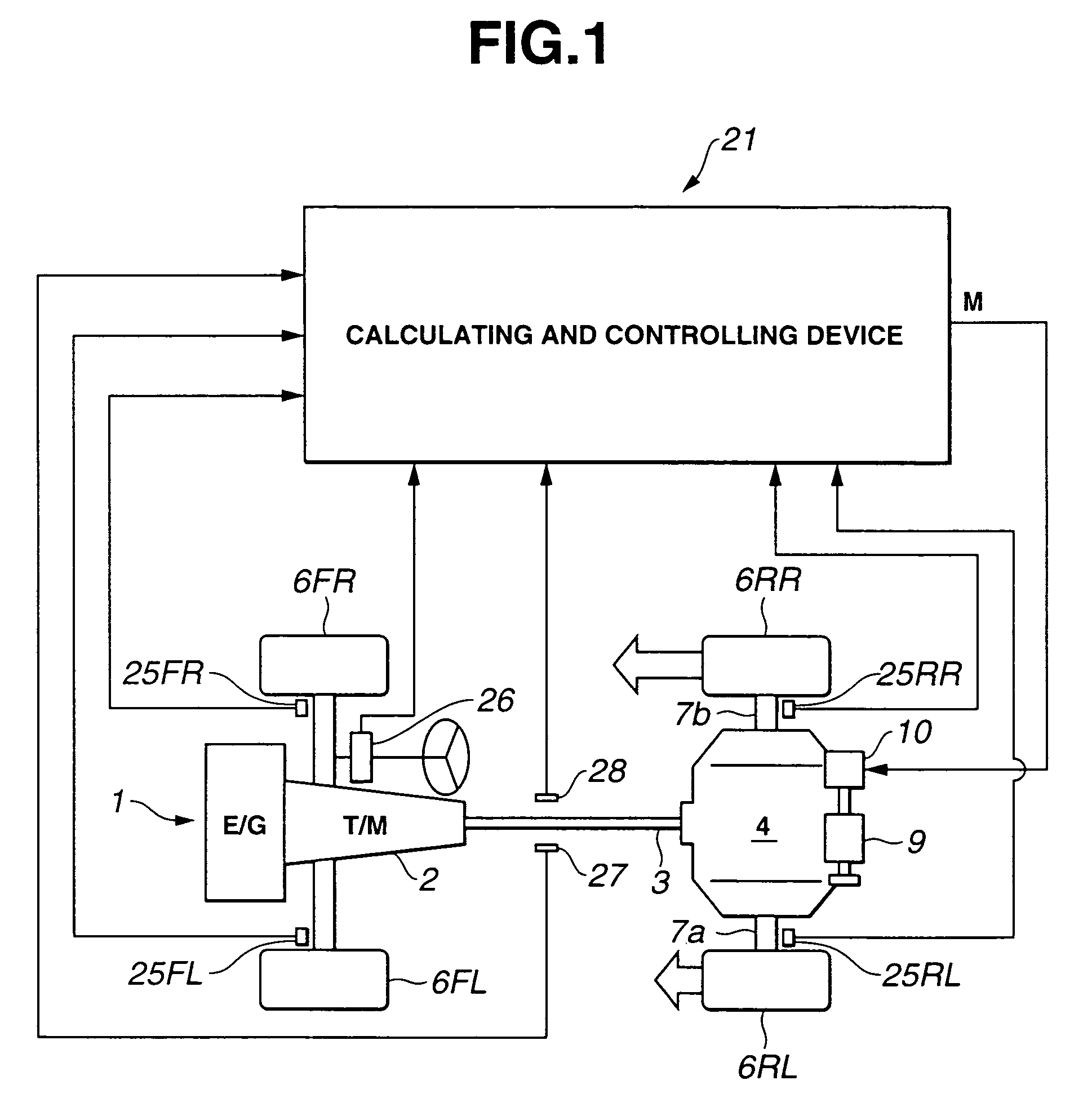
[0020]The structure of the driving-force distribution device 4 of this embodiment will be simply described with reference to FIG. 2. The driving-force distribution device 4 has a differential mechanism 5. The shown differential mechanism 5 is a known planetary gear drive. Rotation of the propeller shaft 3 is transmitted to a differential case 5b via a ring gear 5a of the differential mechanism 5. Next, rotation of the differential case 5b is distri...


PUM


Abstract

A vehicle-behavior detecting apparatus including a first-yaw-moment calculating unit, a second-yaw-moment calculating unit, and an indication-value calculating unit. Based on a linear bicycle model, the first-yaw-moment calculating unit calculates a first-yaw-moment during constant-speed turning. The second-yaw-moment calculating unit reads the longitudinal acceleration detected by an acceleration sensor in addition to the parameters read in the first-yaw-moment calculating unit, and calculates a second yaw moment during acceleration or deceleration. The indication-value calculating unit calculates a variation value in the yaw moment showing the vehicle behavior from the difference between the first yaw moment during constant-speed turning and the second yaw moment during accelerated or decelerated turning. The variation in the yaw moment due to the vehicle-load shift during accelerated or decelerated turning is compensated for by the variation value.

Description

[0001]The disclosure of Japanese Patent Application No. 2003-350089 filed on Oct. 8, 2003; including the specification, drawings and abstract is incorporated herein by reference in its entirety.BACKGROUND OF THE INVENTION[0002]1. Field of the Invention[0003]The present invention relates to a vehicle-behavior detecting apparatus which calculates a variation value in a yaw moment from the difference between the yaw moment during constant-speed turning and the yaw moment during accelerated or decelerated turning, and also relates to a vehicle-behavior controlling apparatus.[0004]2. Description of the Related Art[0005]During constant-speed turning, a vehicle load does not shift in the longitudinal direction greatly, and a nearly constant state is kept. Therefore, a reaction force acting on a steering wheel does not vary greatly. When a driver suddenly presses down on an accelerator pedal to accelerate the vehicle, however, the vehicle load shifts backward, and a vertical load on rear wh...

Claims


Application Information

Patent Timeline
Patent Type & Authority Patents(United States)
IPC IPC(8): G06F7/70G06F19/00B62D6/00B60K23/04B60T8/1755B60W30/00B60W30/02B60W40/10B60W40/109B60W40/114B62D101/00B62D113/00F16H48/08F16H48/26F16H48/36F16H48/38
CPCB60T8/1755B60G2300/082B60G2400/0533B60G2800/016B60G2800/212B60G2800/246B60G2800/952B60T2270/303F16H48/10
Inventor TAKAGI, TOMOHIRO
Owner SUBARU CORP
Why Eureka
Try Eureka