Swing arm assembly with replaceable insert for use with a debarker apparatus

a technology of swing arm and insert, which is applied in the field of debarker apparatuses, can solve the problems of damage to the end damage to the swing arm, and dull edges of the swing arm, and achieve the effects of fast replacement, high wear resistance, and quick replacemen

Active Publication Date: 2008-04-01
NICHOLSON MFG
View PDF21 Cites 16 Cited by
  • Summary
  • Abstract
  • Description
  • Claims
  • Application Information

AI Technical Summary

Benefits of technology

[0009]Some embodiments disclosed herein include the realization that swing arm assemblies of a debarker apparatus can have one or more replaceable inserts. The inserts can be positioned to engage the logs and, thus, may be subjected to cyclic loading. In some embodiments, the inserts are comprised mostly of a high wear resistant material, such as hardened materials, for a prolonged life. If the inserts are not performing properly, the inserts can be quickly replaced. After the inserts have been worn a predetermined amount, for example, the inserts can be quickly replaced resulting in less machine downtime as compared to the downtime required to replace swing arm assemblies or form new leading edges. The inserts can provide suitable high wear surfaces, edges, or other contact regions for engaging logs.

Problems solved by technology

Unfortunately, the leading edges of the swing arms may be damaged due to the applied loads (e.g., the axial loads produced when each of the logs strikes against the swing arms) and frictional interaction with the logs.
After repeated use, the leading edges may become dull, blunt, roughened, or otherwise damaged such that undesirable large frictional forces are present when the leading edges contact the logs.
These frictional forces can prevent proper self-opening of the swing arms and may also damage the ends of the logs.
For example, roughened leading edges can scrape wood from the ends of the logs, thus reducing the amount of usable wood resulting in decreased lumber production.
Unfortunately, because welding often creates irregular surfaces, it may be difficult to form a leading edge sufficiently smooth for consistent self-opening of the swing arms.
Moreover, a lengthy welding process can result in significant machine downtime, thereby reducing lumber production.
Other problems, such as induced residual stresses, reduced toughness (e.g., fracture toughness), and the like, are also associated with welding processes.
Because leading edges are difficult to repair, worn swing arms may be frequently replaced with new swing arms.

Method used


Image

  • Swing arm assembly with replaceable insert for use with a debarker apparatus
  • Swing arm assembly with replaceable insert for use with a debarker apparatus
  • Swing arm assembly with replaceable insert for use with a debarker apparatus

Examples


Embodiment Construction

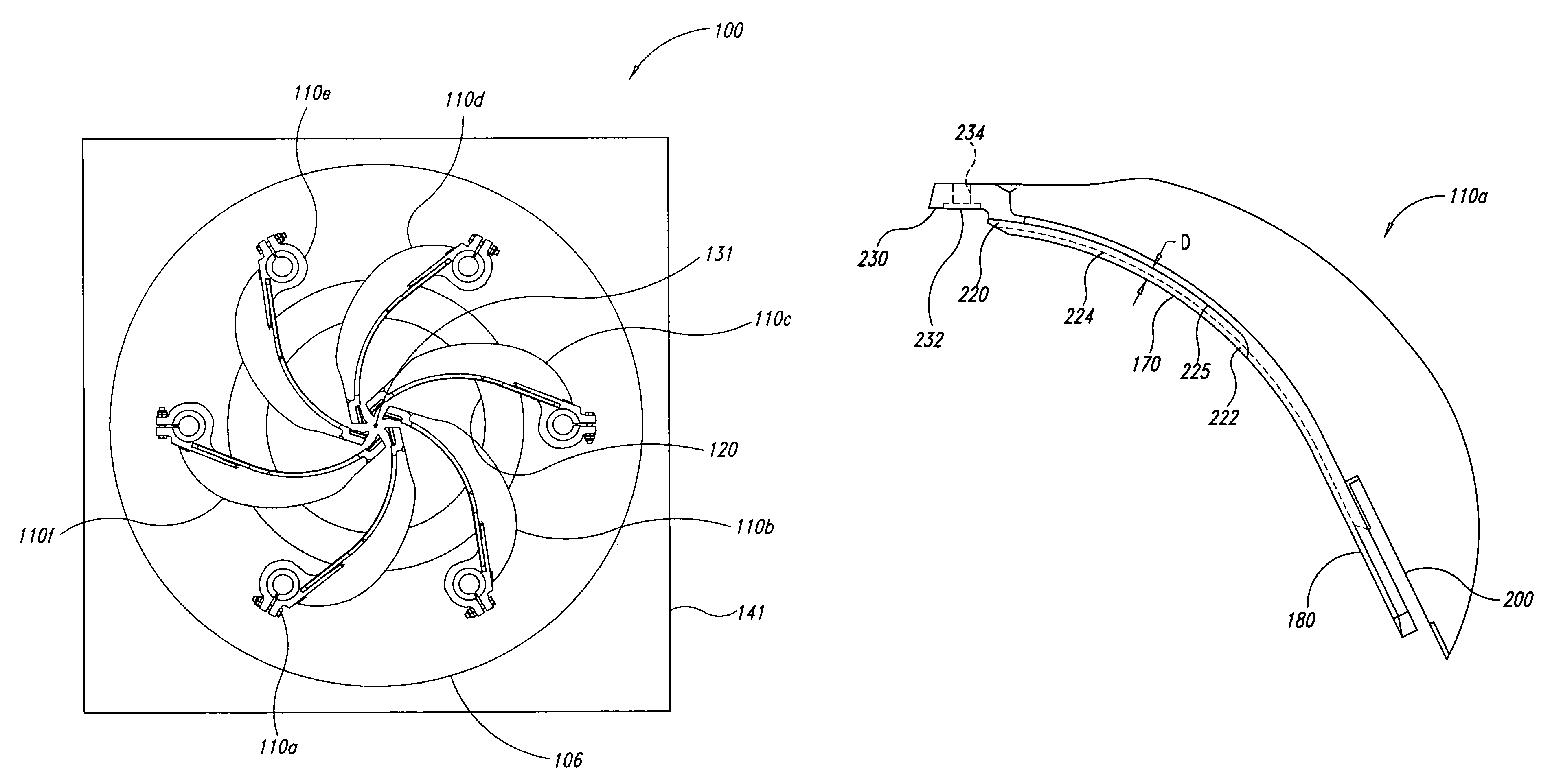
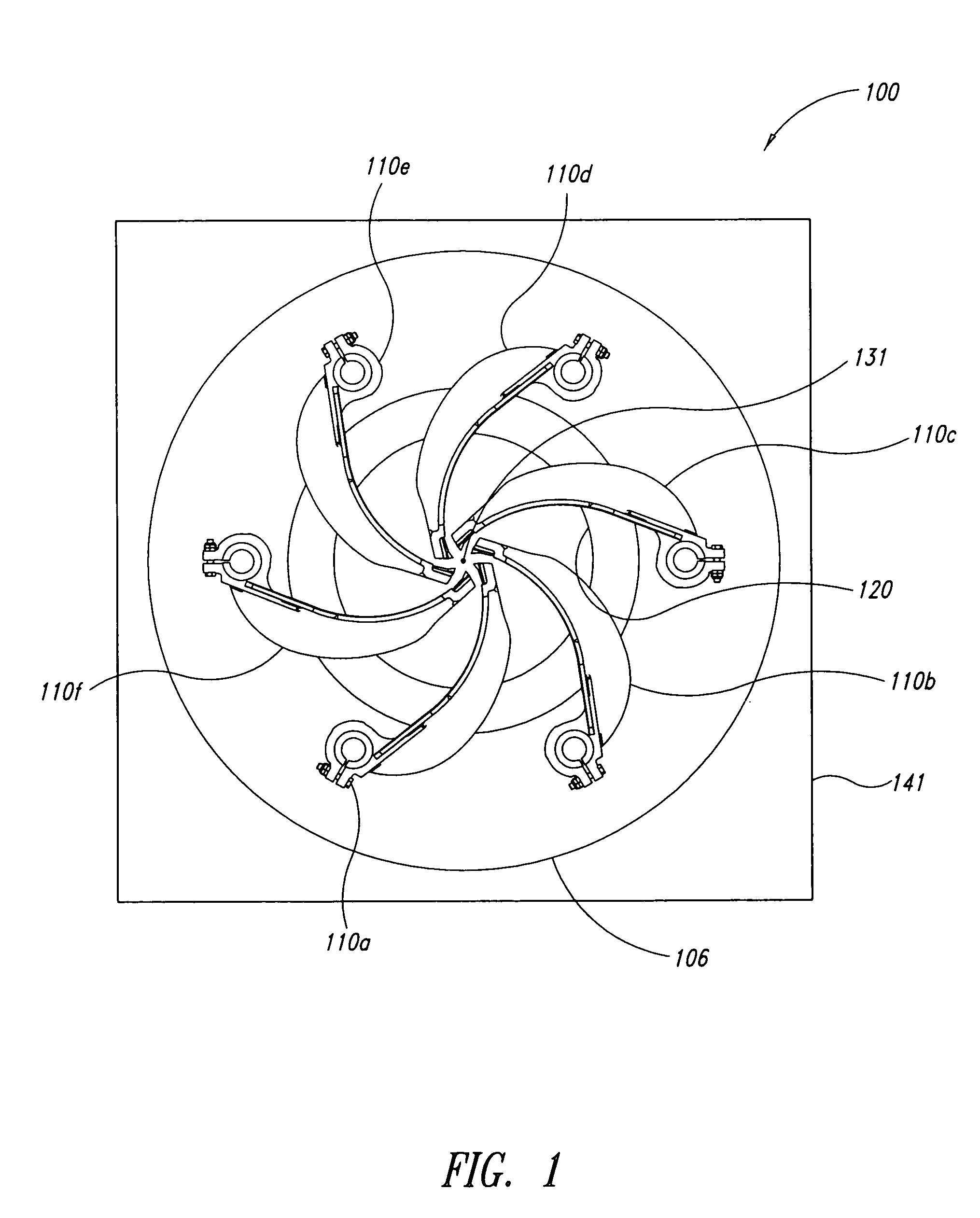
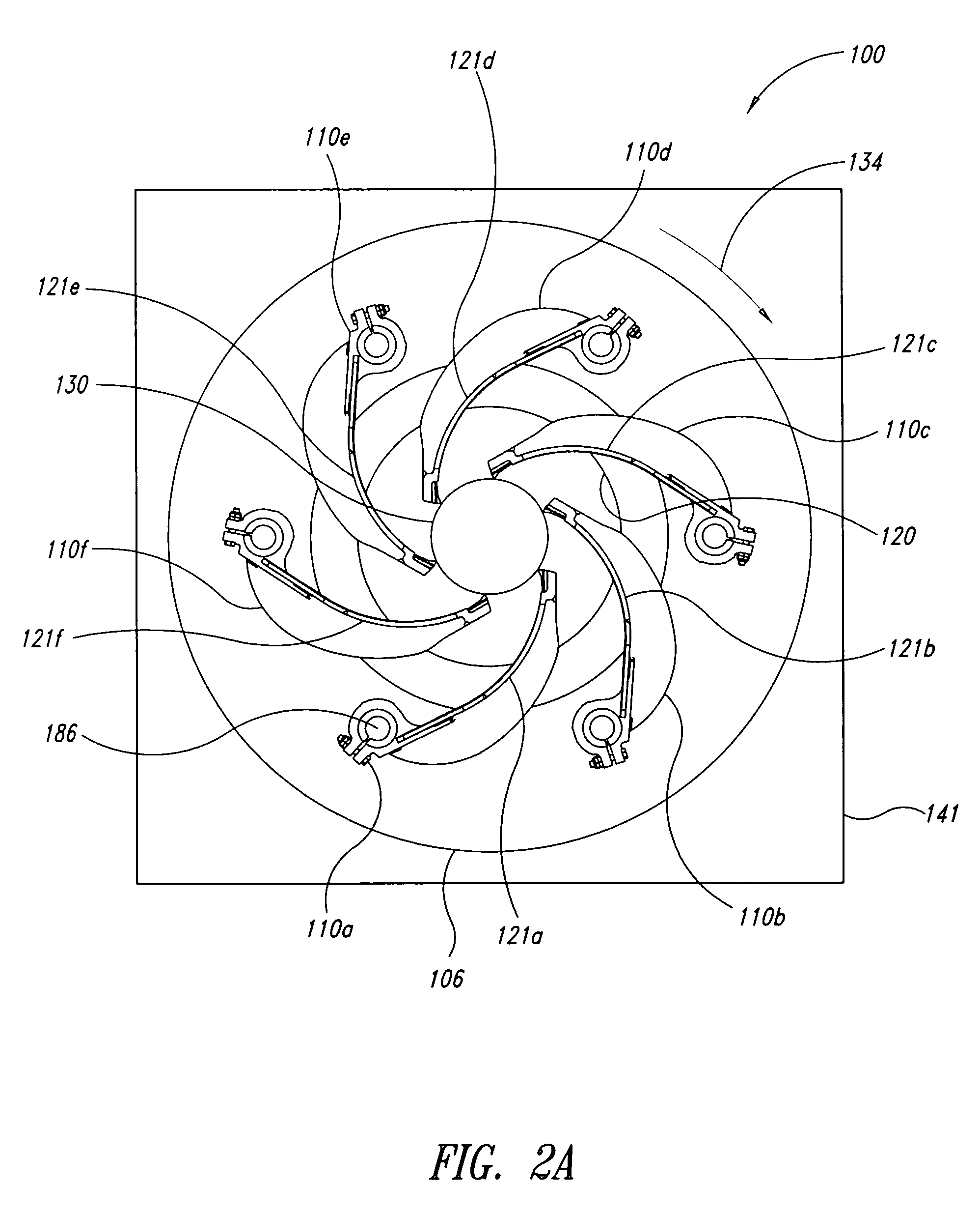
[0029]The present detailed description is generally directed towards a debarker apparatus with a plurality of swing arm assemblies, each having at least one replaceable insert. Some embodiments of the swing arm assemblies have a replaceable insert that defines a contact surface, such as a leading edge, for engaging logs. Many specific details of certain exemplary embodiments are set forth in the following description and in FIGS. 1 to 10 to provide a thorough understanding of such embodiments. One skilled in the art, however, will understand that the disclosed embodiments may be practiced without one or more of the details described in the following description.

[0030]Additionally, the swing arm assemblies are disclosed in the context of log debarkers because they have particular utility in this context. However, the swing arm assemblies can be used in other contexts. For example, the swing arm assemblies can be used to slice bark or otherwise process logs, lumber, and the like. Term...


PUM

PropertyMeasurementUnit
angleaaaaaaaaaa
angleaaaaaaaaaa
angleaaaaaaaaaa

Abstract

Apparatuses, systems, and methods for debarking logs are shown and described. The disclosed embodiments can be used for quickly and conveniently replacing contact surfaces, such as leading edges, of swing arm assemblies. Some disclosed embodiments include a swing arm assembly having a replaceable insert that defines a leading edge for engaging logs moving along a processing line. The insert can be made of a wear resistant material for a prolonged life. A worn insert can be replaced with another insert to ensure proper functioning of the debarker.

Description

BACKGROUND[0001]1. Technical Field[0002]The present disclosure in some embodiments generally relates to debarker apparatuses, and more specifically to debarker apparatuses having swing arm assemblies with replaceable inserts.[0003]2. Description of the Related Art[0004]Rotary log debarkers, commonly referred to as ring debarkers, are used to remove bark from logs to facilitate processing of the logs into lumber and other wood products. Rotary log debarkers often have an array of swing arms pivotally mounted to a rotatable outer ring. Each of the swing arms has a tip for scraping bark from the logs.[0005]As a log moves along a processing line of a traditional debarker, the advancing log contacts and pushes against the leading edges of the swing arms carried by the rotating outer ring. The log then drives the swing arms outwardly until the tips of the swing arms engage the periphery of the log. In this manner, swing arms can be self-opened. Once opened, the swing arms are urged inward...

Claims


Application Information

Patent Timeline
Patent Type & Authority Patents(United States)
IPC IPC(8): B27L1/00
CPCB27L1/08Y10T29/49826
Inventor CHOLEWCZYNSKI, MAREKLEFSRUD, JORGEN
Owner NICHOLSON MFG
Why Eureka
Try Eureka