
Automatic and continuous unwinder device for supplying web-like material from reels

a technology of unwinding device and reel, which is applied in the direction of transportation and packaging, thin material processing, filament handling, etc., can solve the problem that the reel is not equipped with a supporting, unlike the usual device, and the reel is not equipped with a support. , to achieve the effect of rapid and reliable feeding and no halting

Inactive Publication Date: 2008-04-01
IDAQS BIOTECH INC +1
View PDF17 Cites 30 Cited by
  • Summary
  • Abstract
  • Description
  • Claims
  • Application Information

AI Technical Summary

Benefits of technology

[0012]In accordance with a first aspect, the object of this invention is to provide an unwinder device that permits the substitution of an empty reel with a new reel of web-like material in a rapid and reliable manner, without significantly slowing the feed speed of the web-like material itself to the production line downstream of the unwinder, and in any case without halting the feeding.

Problems solved by technology

The shuttle, unlike usual devices, is not equipped with supports that hold the reel during unwinding.

Method used


Image

  • Automatic and continuous unwinder device for supplying web-like material from reels
  • Automatic and continuous unwinder device for supplying web-like material from reels
  • Automatic and continuous unwinder device for supplying web-like material from reels

Examples


Embodiment Construction

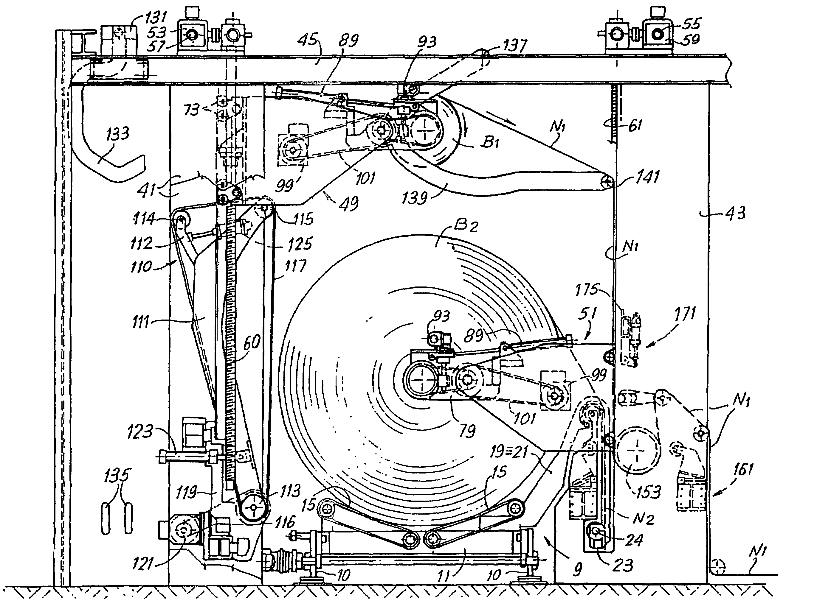
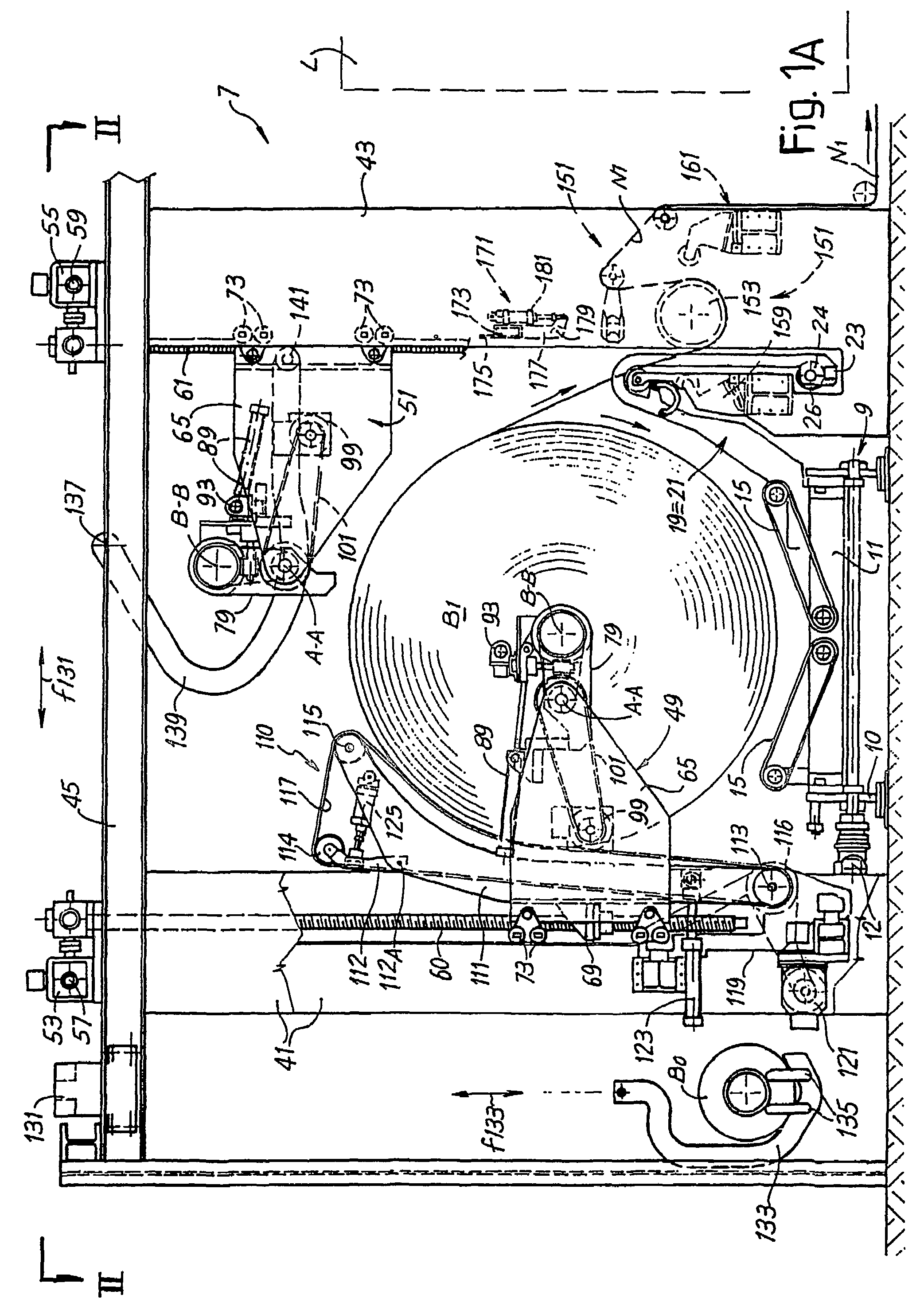
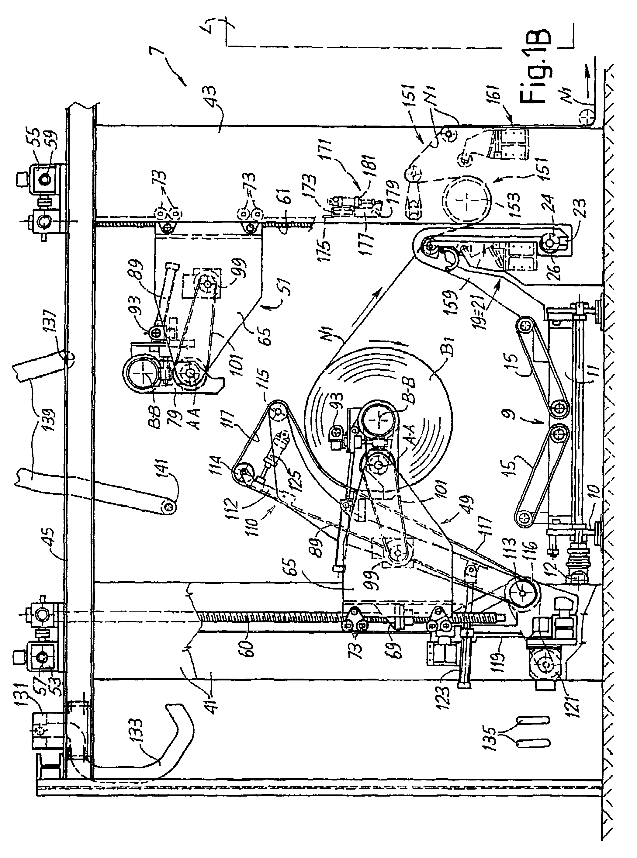
[0051]The unwinder device in accordance with the invention, generically indicated by reference 1, in the illustrated example includes a loading station 3 arranged at the side of an unwinding station 7. A shuttle or carriage 9 (see FIG. 2 in particular) is provided with reciprocating translatory motion in the directions of the double arrow f9 for moving between the loading station 3 and the unwinding station 7. With specific reference to the plan view in FIG. 2, by moving the shuttle 9 to the right it can transfer the reel B2 to the unwinding station 7.

[0052]As can be seen in FIGS. 3 and 4 in particular, where the shuttle 9 is shown separately from the other members of the unwinder device, the shuttle has a structure or frame 11 equipped with wheels 10 driven by a motor 12 that provides motion in the directions of the double arrow f9. On the frame 11, support belts 15 with a V-shaped arrangement are provided to create a support cradle for the reels. Each reel placed on the shuttle 9 ...


PUM

PropertyMeasurementUnit
peripheral speedsaaaaaaaaaa
vertical movementaaaaaaaaaa
suctionaaaaaaaaaa

Abstract

The unwinder device includes an unwinding station (7), with unwinding members for unwinding reels and a splicing device (151) for splicing together web-like materials (N1 and N2) coming from a first reel (B1) and from a second reel (B2). At least two supports (49, 51) are arranged in the unwinding station for the respective reels of web-like material, associated with respective unwinding members (83, 99). The supports are constructed and arranged to simultaneously support two reels being unwound, during at least a phase of the unwinding, and each of said supports is able and constructed to load a new reel in an engagement position, support it during the unwinding and unload it in a release position.

Description

TECHNICAL FIELD[0001]This invention concerns an unwinder device for unwinding reels of web-like material wound around a central spindle for supplying web-like material to a converting or processing line.[0002]The invention also concerns a method for unwinding reels of web-like material and for feeding the unwound material to a converting or processing line.STATE OF THE ART[0003]In many industrial applications, there is a requirement to feed a production line with a web-like material that is unwound from a reel or multiple reels in parallel. Typically, the feeding of web-like material is requested in the paper industry. For example, for the production of paper serviettes, rolls of toilet paper, kitchen rolls or the like, converting lines are provided in which a web-like material is supplied from a reel of large diameter and very long axial length to a series of stations downstream, at the end of which the finished product is obtained. In the case of rolls of toilet paper and similar ...

Claims


Application Information

Patent Timeline
Patent Type & Authority Patents(United States)
IPC IPC(8): B65H19/12B65H19/18
CPCB65H19/126B65H2301/4132B65H2301/41346B65H2301/41394B65H2301/41468B65H2301/4185B65H2405/421B65H2405/422B65H2406/31B65H19/12B65H16/06
Inventor BENVENUTI, ANGELOMORELLI, ROBERTOMADDALENI, ROMANO
Owner IDAQS BIOTECH INC
Learn More