
Fluid-filled type vibration-damping device

a technology of vibration-damping device and fluid-filled filling, which is applied in the direction of shock absorbers, machine supports, jet propulsion mountings, etc., can solve the problems of reducing the ability of vibration-damping capability based on fluid flow through the orifice passage, affecting the stability of the orifice, and unable to exhibit adequate vibration-damping performance. , to achieve the effect of adequate durability of elastic rubber film, ample recovery force and outstanding flexibility

Active Publication Date: 2008-04-01
SUMITOMO RIKO CO LTD
View PDF7 Cites 17 Cited by
  • Summary
  • Abstract
  • Description
  • Claims
  • Application Information

AI Technical Summary

Benefits of technology

The device achieves enhanced vibration damping capabilities across a wider frequency range with improved durability and flexibility, allowing for effective absorption of fluid pressure and rapid recovery of the elastic rubber film, even under negative pressure conditions.

Problems solved by technology

However, upon input of vibrations in a frequency range higher than the tuning frequency, the orifice passage becomes substantially blocked off, which can result in considerably increased dynamic spring constant, thereby making it difficult to exhibit adequate vibration damping performance.
In a fluid-filled type vibration-damping device having a movable rubber film, there is a risk that elastic deformation of the movable rubber film may also absorb even pressure fluctuations produced within the pressure-receiving chamber during input of vibration of the frequency range to which the orifice passage is tuned.
As a result, vibration-damping capability based on fluid flow through the orifice passage may be diminished.
Extensive studies conducted by the inventors, however, has revealed that the use of such a movable rubber film creates a new problem.
That is, where the movable rubber film is made sufficiently pliable with reference to the required characteristics of the movable rubber film in order to produce a low dynamic spring constant, the movable rubber film may suffer from insufficient elasticity.
In this state, the movable rubber film does not recover its original shape prior to suction after the suction created by the negative pressure is released, and cannot exhibit the desired performance.
However, since there is backflow of gas and oil from the combustion chamber end into the air intake passage of the internal combustion engine, there is a risk that gas or oil will flow into the air chamber of the fluid-filled type vibration-damping device.
However, movable rubber films produced from such materials are relatively stiff, and where it is attempted to impart the desired characteristics, it becomes difficult to provide thickness adequate to ensure a sufficient level of durability.
On the other hand, where the movable rubber film using materials like those described above to impart oil resistance and thickness sufficient to ensure durability, the movable rubber film becomes highly rigid, which not only makes it difficult to meet the requirement of low spring characteristics.
In addition, due to the lower pliability also poses a risk of rupture or other damage due to repeated elastic deformation by negative pressure suction.

Method used


Image

  • Fluid-filled type vibration-damping device
  • Fluid-filled type vibration-damping device
  • Fluid-filled type vibration-damping device

Examples


Embodiment Construction

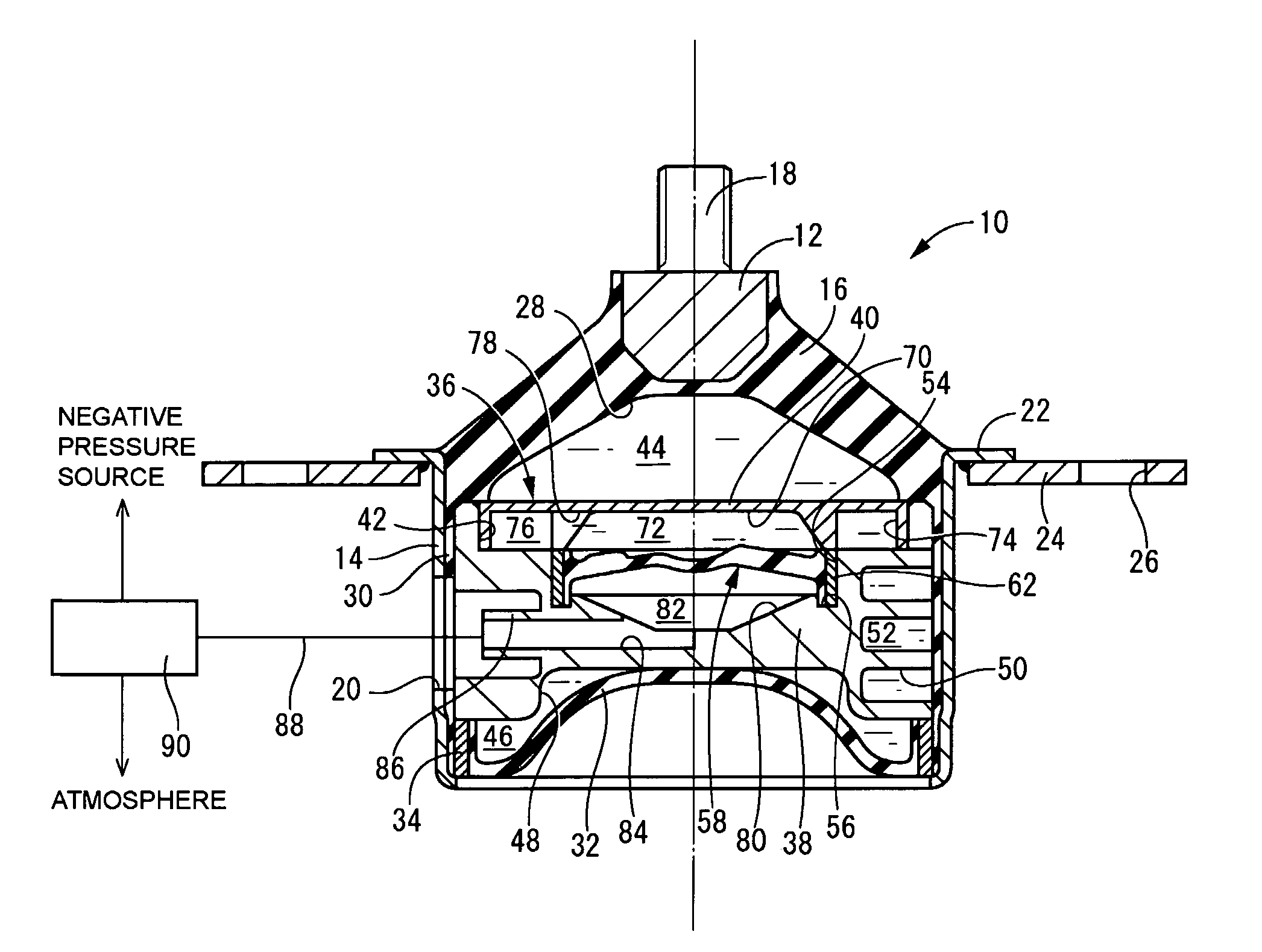
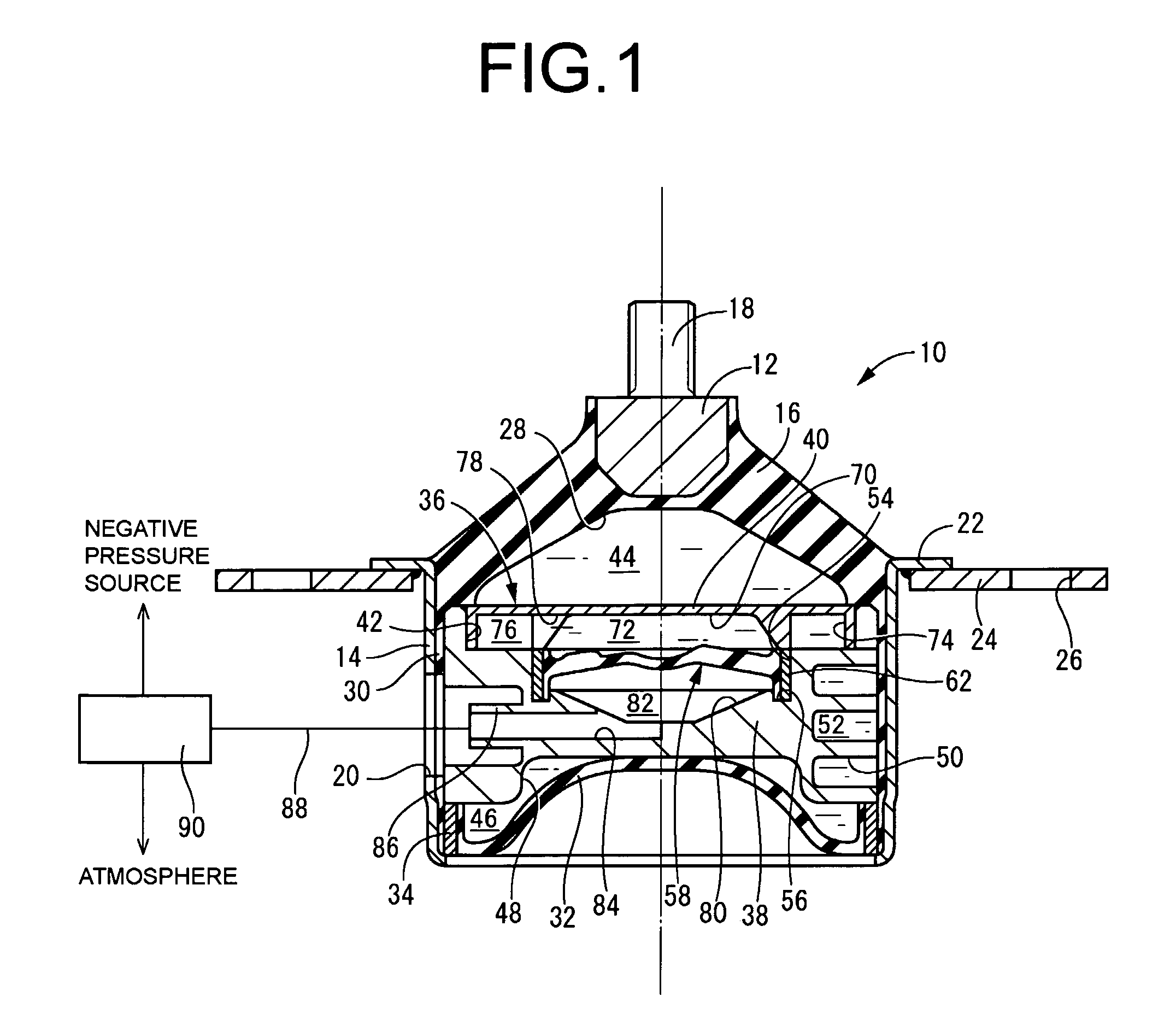
[0043]Referring first to FIG. 1, there is shown a fluid-filled vibration-damping device in the form of an automotive engine mount 10 as a first embodiment of the invention. The engine mount 10 is constructed of a first mounting member 12 of metal and a second mounting member 14 of metal, connected together by a main rubber elastic body 16. The engine mount 10, in cooperation with another engine mount not shown in the drawings, supports a power unit on a body of the vehicle in a vibration damped manner, with the first mounting member 12 attached to the power unit side and the second mounting member 14 attached to the body side. In the installed state, the engine mount 10, in association with elastic deformation of the main rubber elastic body 16 due to input of the distributed load of the power unit, undergoes relative displacement of the first mounting member 12 and the second mounting member 14 so that these move closer to one another a certain amount in the vertical direction in F...


PUM


Abstract

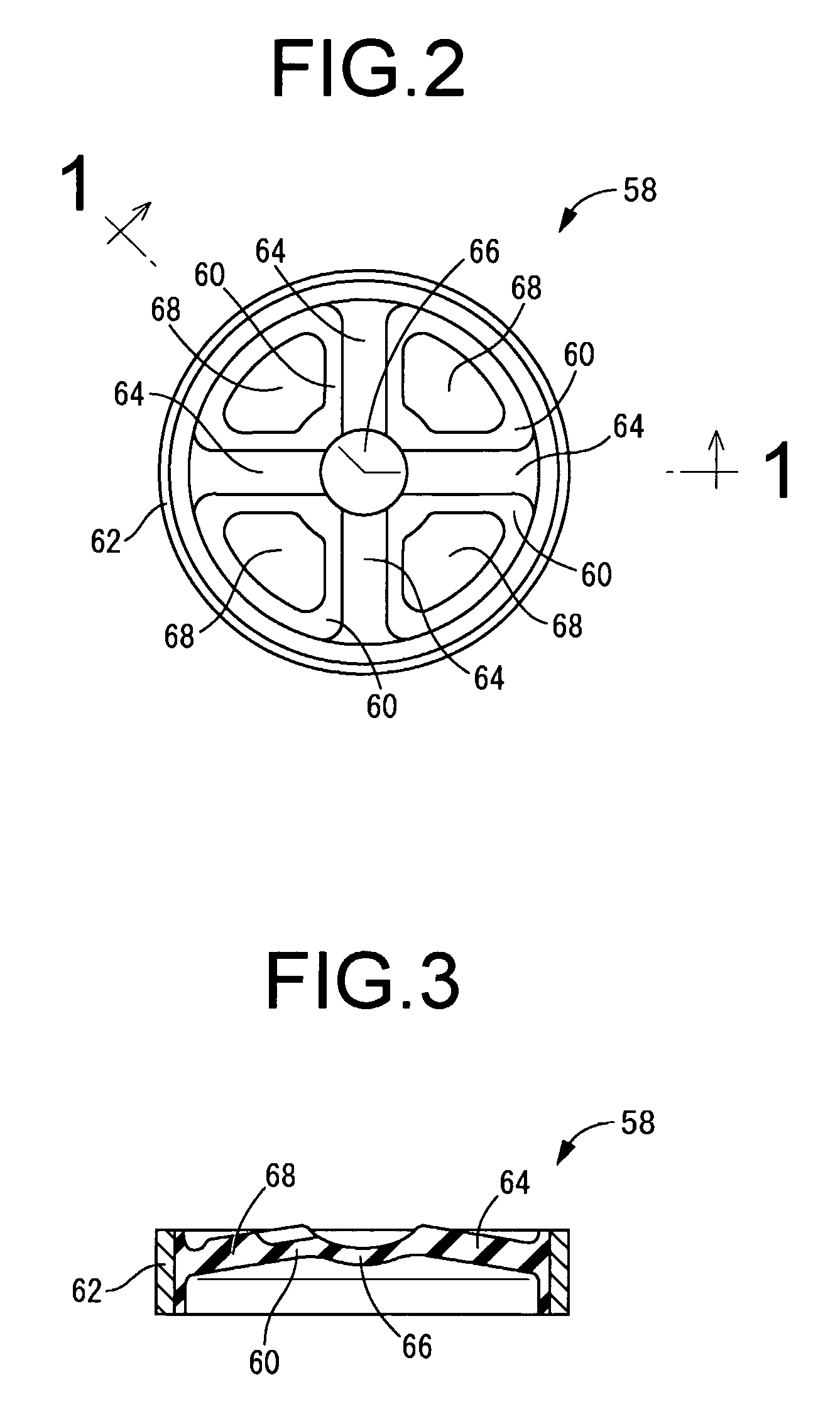
A fluid-filled type vibration-damping device having an elastic rubber film partially defining a primary fluid chamber at one surface and partially defining a pressure action chamber. The pressure action chamber varies its pressure under control so that the elastic rubber film changes its elasticity to change damping characteristics of the device. To give sufficient recovery force for the elastic rubber film, the elastic rubber film includes a plurality of thick reinforcing ribs circumferentially spaced apart from one another and extending in a radial direction from an outside peripheral edge over a length not reaching a center so that areas situated between pairs of adjacent reinforcing ribs constitutes thin portions formed by a thin rubber elastic body, while the center portion of the elastic rubber film situated between distal ends constitutes a bowed center portion thinner than the reinforcing ribs and convex towards the pressure action chamber.

Description

INCORPORATED BY REFERENCE[0001]The disclosure of Japanese Patent Application No. 2005-075863 filed on Mar. 16, 2005 including the specification, drawings and abstract is incorporated herein by reference in its entirety.BACKGROUND OF THE INVENTION[0002]1. Field of the Invention[0003]The present invention relates generally to a fluid-filled type vibration-damping device for connecting in a vibration-damping fashion a vibration damping member with a member to be vibration-damped. More particularly, the invention is concerned with a fluid-filled type vibration-damping device having a flexible film as a fluid pressure absorbing mechanism.[0004]2. Description of the Related Art[0005]Rubber vibration dampers having a first mounting member and a second mounting member connected by a main rubber elastic body are widely employed in a variety of fields as vibration-damped connectors or vibration-damped supports for installation between members making up a vibration transmission system. As one ...

Claims


Application Information

Patent Timeline
Patent Type & Authority Patents(United States)
IPC IPC(8): F16F13/26B60K5/12
CPCF16F13/105F16F13/26
Inventor MURAMATSU, ATSUSHIMAENO, HAJIMEMURAOKA, MUTSUMIKOYAMA, HIRONORI
Owner SUMITOMO RIKO CO LTD
Learn More