Microfluidic device and method with trapping of sample in cavities having lids that can be opened or closed

a microfluidic device and sample technology, applied in the direction of positive displacement liquid engine, library member identification, energy-based chemical/physical/physico-chemical process, etc., can solve the problems of poor quality, method, although fairly fast and cheap, and the number of out coming events is immense, so as to enhance detection sensitivity and improve the effect of “

Inactive Publication Date: 2008-04-01
OTILLAR ROBERT
View PDF30 Cites 38 Cited by
  • Summary
  • Abstract
  • Description
  • Claims
  • Application Information

AI Technical Summary

Benefits of technology

[0016]A main objective of the present invention is to provide an arrangement that improves the “one by one” experimentation through enhancing the detection sensitivity.
[0017]The technique allows a relatively rapid screening of new chemicals to be used as drugs, both with regard to their function and, importantly, with regard to the determination of the side effects that a given drug might exert. The technique can also be used in many other applications such as genome determination, proteomics and others.
[0018]In an arrangement configured according to the invention, it is relatively easy to change both the dimensions and the number of the wells. Also, the simplicity of the design will allow integrating the reaction product detection system, on-chip, and perhaps also the facility for multi-well deposition of the active substance.

Problems solved by technology

Some of these mutations are important for the cell-well being, but others are dangerous, for instance, cancerous mutations.
In all of these processes, the number of out coming events is immense.
This method, although fairly fast and cheap, produces a permanent pattern on a matrix which will be used up after a single experiment.
In reality this number is much lower (around 20% of best results) due to the very poor quality of even the best matrices produced to date.
However, the drawback is that the detection is not sensitive, as other molecules will also be detected.

Method used


Image

  • Microfluidic device and method with trapping of sample in cavities having lids that can be opened or closed
  • Microfluidic device and method with trapping of sample in cavities having lids that can be opened or closed
  • Microfluidic device and method with trapping of sample in cavities having lids that can be opened or closed

Examples


Embodiment Construction

[0039]A basic idea of the present invention is to present an arrangement which enhances detection and analysis by reducing the number of error sources. Surprisingly, it has been achieved by attracting some samples to a section and repelling the samples not achieved; e.g., a reaction with an agent in the section.

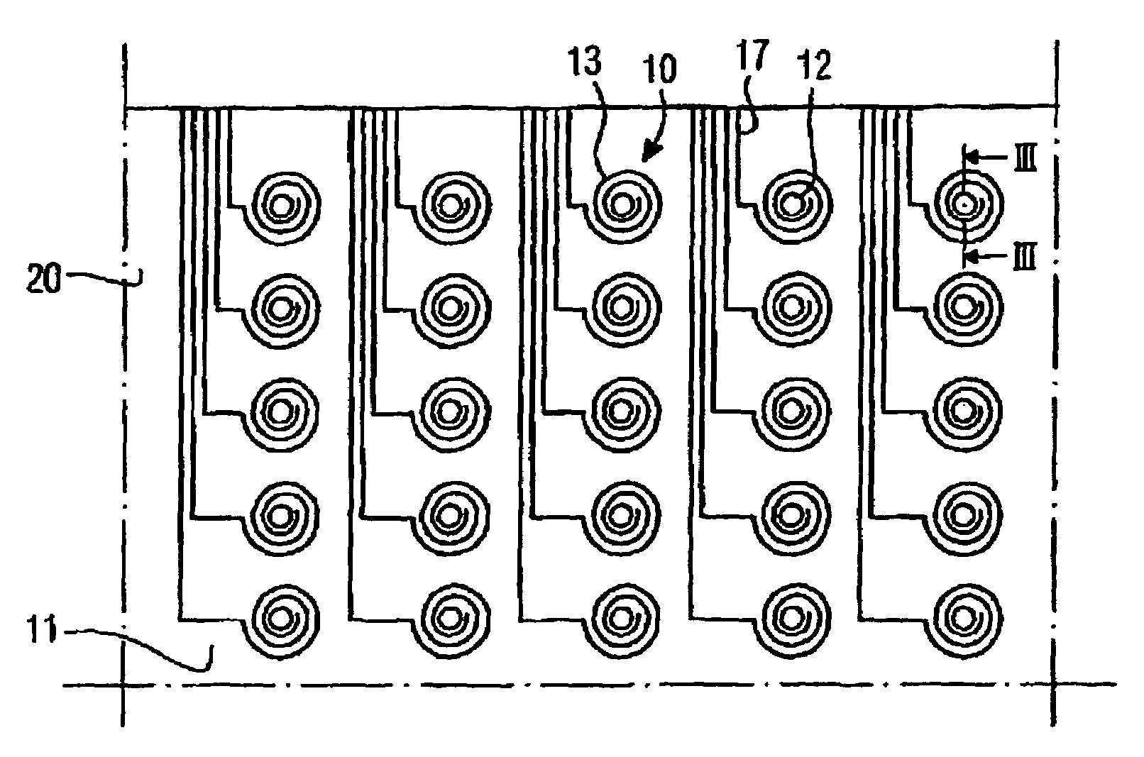
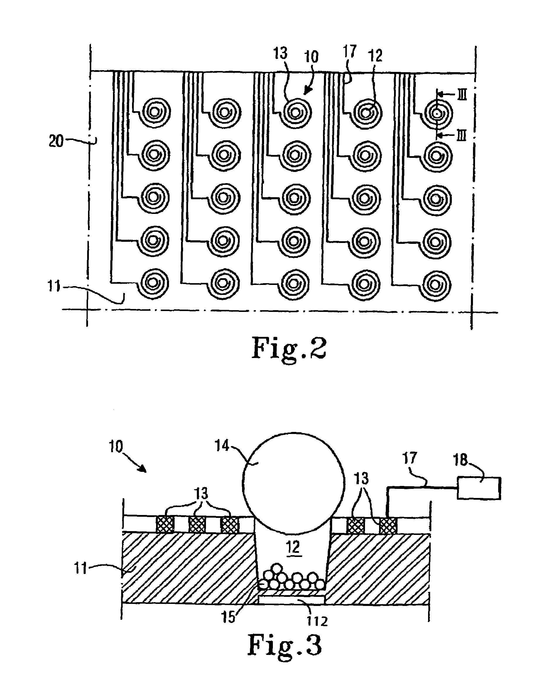
[0040]FIGS. 2 and 3 illustrate a preferred example of an arrangement configured according to the invention. FIG. 2 illustrates an enlarged schematic view of a part of chip 19 including a number of sample collecting arrangements 10. Each sample collecting arrangement includes a cavity (crater, pocket, or well) 12 provided in a substrate 11, and means 13 to control the cap (lid or cover) 14. Each control means 13 is connected to controller 18 (FIG. 3) through connections 17.

[0041]FIG. 3 is a schematic cross-section through the device 10. However, the device 10 is shown in a stage where samples 15 are collected and the crater 12 is closed by means of the lid or closure 14. The s...


PUM

PropertyMeasurementUnit
diametersaaaaaaaaaa
diametersaaaaaaaaaa
sizeaaaaaaaaaa

Abstract

Method and arrangement (10, 20) for preparing samples (15, 27) submergible in a liquid medium. The arrangement includes a carrier structure (11). The carrier includes a device (13, 23) for controllable generation of a magnetic field through influence of a control signal to attract at least part of the at least first and second type of samples (15, 27) towards specific locations on the carrier when connected to a first control signal and to repel at least one of the first or second type of samples when connected to a second control signal.

Description

CROSS REFERENCE TO RELATED APPLICATIONS[0001]This application is a continuation patent application of International Application No. PCT / SE01 / 01799 filed 23 Aug. 2001 which was published in English pursuant to Article 21(2) of the Patent Cooperation Treaty, and which claims priority to Swedish Application No. 0002990-0 filed 23 Aug. 2000 and to U.S. Provisional Application No. 60 / 228,015 filed 24 Aug. 2000. Said applications are expressly incorporated herein by reference in their entireties.BACKGROUND OF INVENTION[0002]1. Technical Field of the Invention[0003]The present invention relates to a method and arrangement for enhancing detection of different samples including at least first or second types of samples.[0004]2. Background of the Invention[0005]When considering a living organism, for example a human being, an animal or even a plant, a basic subunit of such organisms is a cell. One way to categorize such cells is by the functions they are aimed to perform in an organism; e.g.:...

Claims


Application Information

Patent Timeline
Patent Type & Authority Patents(United States)
IPC IPC(8): G01N33/553G01N1/00B01J19/00B01L3/00B03C1/035C12M1/00C12Q1/68C40B20/02C40B40/06C40B60/14G01N1/02G01N27/00G01N27/22G01N33/543G01N37/00
CPCB01J19/0046B01J19/0093B01L3/502761B01L3/50853B03C1/035G01N33/54333B01J2219/00317B01J2219/0034B01J2219/00439B01J2219/00459B01J2219/005B01J2219/00585B01J2219/0059B01J2219/00596B01J2219/00605B01J2219/00608B01J2219/00612B01J2219/00621B01J2219/00648B01J2219/00659B01J2219/00689B01J2219/00722B01J2219/00783B01J2219/00822B01J2219/00828B01J2219/00833B01J2219/00914B01J2219/00918B01J2219/0093B01J2219/00934B01J2219/0095B01L2200/0647B01L2300/049B01L2300/0819B01L2400/043B01L2400/0433C12Q1/6825C40B40/06C40B60/14
Inventor STOREK, DAVIDSCHNEEBERGER, NIKLAUSOTILLAR, JR., ROBERT P.KROZER, ANATOL
Owner OTILLAR ROBERT
Why Eureka
Try Eureka