Method for manufacturing plasma display panel

Inactive Publication Date: 2010-08-12
PANASONIC CORP
View PDF7 Cites 2 Cited by
  • Summary
  • Abstract
  • Description
  • Claims
  • Application Information

AI Technical Summary

Benefits of technology

[0010]According to such a manufacturing method, the metal oxide paste excellent in dispersion, printability, and flammability allows discrete and uniform attachment of the aggregated particles of the metal oxide particles within the surface of the primary film, thereby to uniform a coverage distribution within the surface.
[0011]This results in provision of a PDP that improves the electron emission characteristics, while having electric charge retention characteristics, and is capable of achieving both a high image quality and low cost as well as a low voltage, so as to realize a PDP with low power consumption as well as with high-definition / high-luminance display performance.

Problems solved by technology

Since characteristics of electron emission from the protective layer determine an image quality of a PDP, controlling the electron emission characteristics is a critically important issue.

Method used


Image

  • Method for manufacturing plasma display panel
  • Method for manufacturing plasma display panel
  • Method for manufacturing plasma display panel

Examples


embodiment

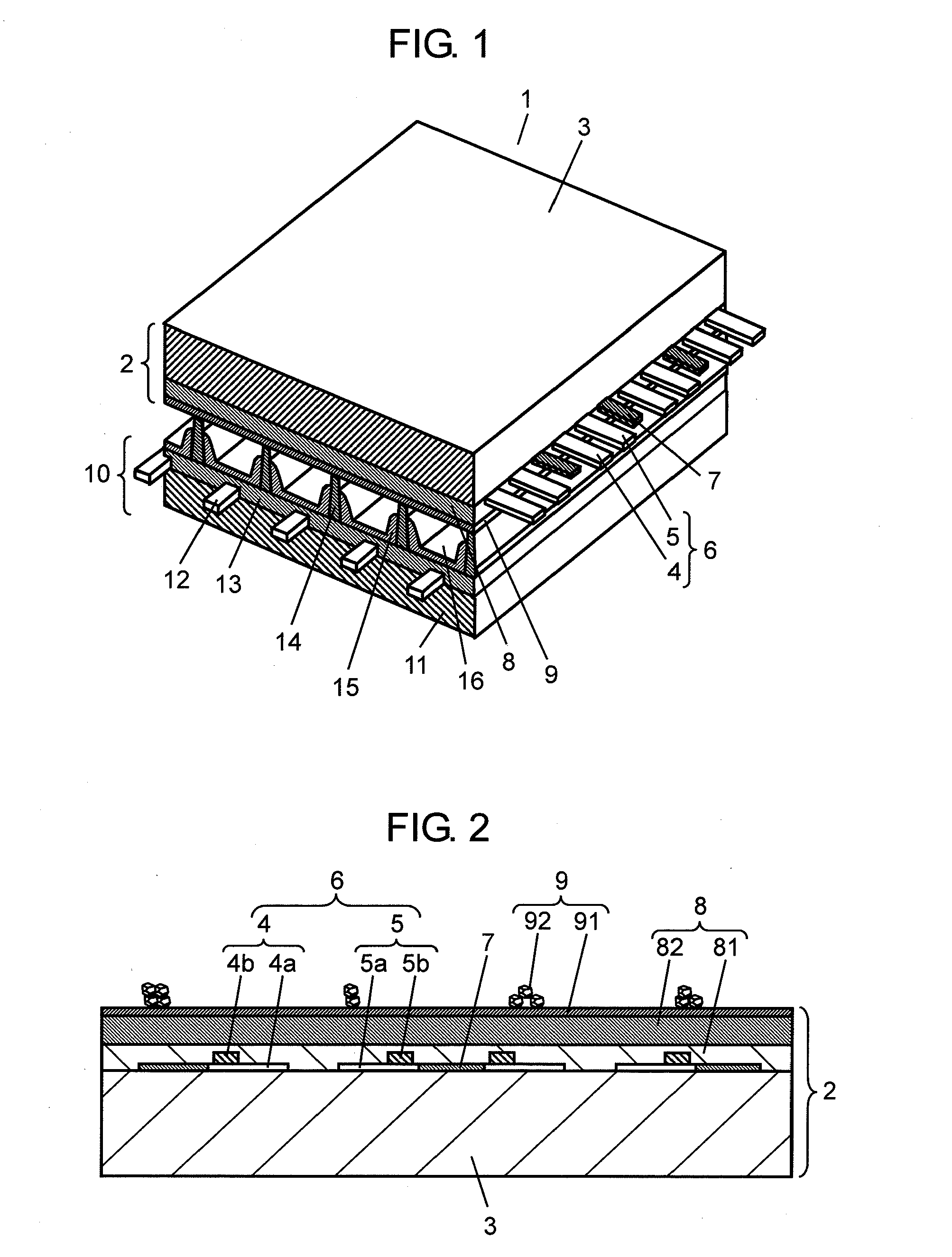
[0023]FIG. 1 is a perspective view showing a structure of PDP 1 manufactured with a method for manufacturing a PDP in an embodiment of the present invention. Front panel 2 made up of front glass substrate 3 and the like and rear panel 10 made up of rear glass substrate 11 and the like are opposed to each other, and a peripheral section of those panels is sealed in an airtight manner with a sealing agent made of glass frit or the like. Discharge space 16 inside PDP 1 is filled with discharge gas of Neon (Ne), Xenon (Xe), and the like at a pressure of 53.3 kPa to 80.0 kPa. On front glass substrate 3 of front panel 2, a plurality of pairs of belt-like display electrodes 6, each made up of scan electrode 4 and sustain electrode 5, are arranged in parallel with a plurality of black stripes (light proof layers) 7. Dielectric layer 8 that functions as a capacitor is formed on front glass substrate 3 so as to cover display electrodes 6 and light proof layers 7, and further on the surface of...


PUM


Abstract

In order to realize a plasma display panel with high-definition / high-luminance display performance as well as with low power consumption, after formation of a primary film, a metal oxide paste made up of aggregated particles of metal oxide particles, an organic resin component, and diluting solvent is applied and fired. Thereby, a plurality of aggregated particles of the metal oxide particles are attached and formed onto the primary film. The metal oxide paste is obtained by mixing a first metal oxide paste with a content of the aggregated particles of the metal oxide, the organic resin component, and the diluting solvent being not smaller than 1.5 vol % and a second metal oxide paste made up only of the organic resin component and the diluting solvent.

Description

TECHNICAL FIELD[0001]The present invention relates to a method for manufacturing a plasma display panel.BACKGROUND ART[0002]Among flat panel displays (FPDs), a plasma display panel (hereinafter referred to as a PDP) is capable of performing a high-speed display and easy to increase in size, thus having been in widespread commercial use in fields of a video display device, a publicity display device, and the like.[0003]A typical AC-driven surface discharge type PDP adopts a triode structure, being a structure in which two glass substrates, a front panel and a rear panel, are opposed to each other with a predetermined spacing therebetween. The front panel is configured of; display electrodes made up of striped scan electrodes and sustain electrodes formed on a glass substrate; a dielectric layer covering the display electrodes and working as a capacitor for accumulating electric charges; and a protective layer having a thickness of the order of 1 μm and formed on the dielectric layer....

Claims


Application Information

Patent Timeline
IPC IPC(8): H01J9/00H01J9/02H01J11/12H01J11/22H01J11/24H01J11/26H01J11/34H01J11/40
CPCH01J9/02H01J11/40H01J11/12
Inventor KIGAMI, KENGOSHINICHIRO, ISHINOKOYO, SAKAMOTOHIDEJI, KAWARAZAKIKANAME, MIZOKAMIYUICHIRO, MIYAMAEYOSHINAO, OOE
Owner PANASONIC CORP
Why Eureka
Try Eureka