
Multiband planar antenna

Inactive Publication Date: 2008-04-01
CANTOR FITZGERALD SECURITIES
View PDF9 Cites 84 Cited by
  • Summary
  • Abstract
  • Description
  • Claims
  • Application Information

AI Technical Summary

Benefits of technology

[0013]The invention has the advantage that the structural part by which the matching of the antenna is improved on the upper operating band, also improves the matching and efficiency on the lowest operating band. This is based on the additional inductance, which the loop conductor operating as a part of the feed conductor of the PIFA introduces into it. A slight extension of the ground plane would have a similar effect, but the size of the device does not allow it. In addition, the invention has the advantage that the resonance of the loop and the upper resonance of the PIFA hardly interfere each other, in which case their frequencies can be arranged close to each other. This is due to the location of the structural part corresponding to the lowest operating band between the parts mentioned above. Furthermore, the invention has the advantage that the structure according to it does not require additional conductors, such as a second short-circuit conductor between the radiating plane and the other part of the radio device at issue.

Problems solved by technology

A slight extension of the ground plane would have a similar effect, but the size of the device does not allow it.

Method used


Image

  • Multiband planar antenna
  • Multiband planar antenna
  • Multiband planar antenna

Examples


Embodiment Construction

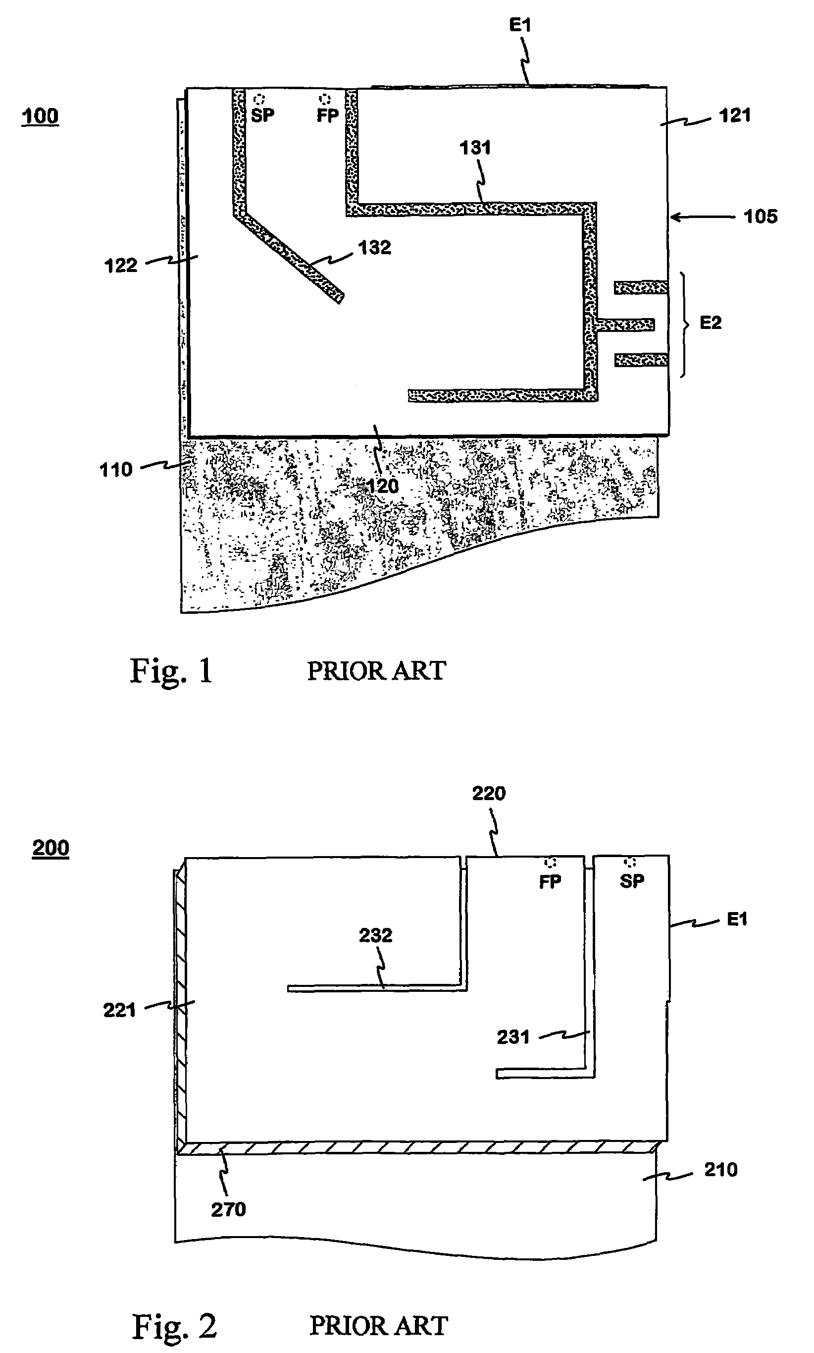
[0023]FIGS. 1 and 2 were already discussed in connection with the description of the prior art.

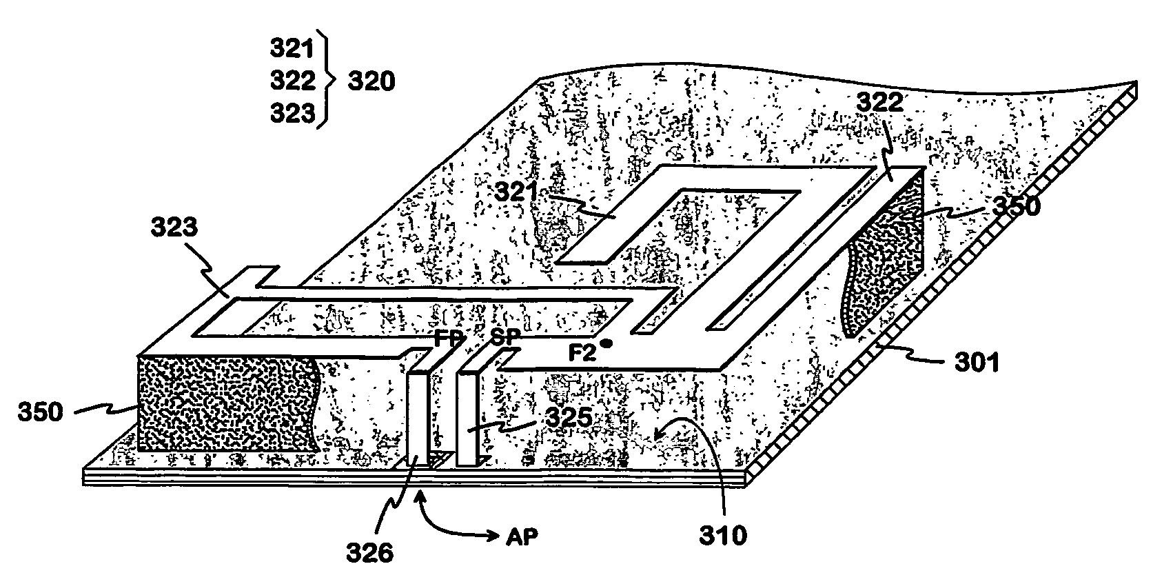
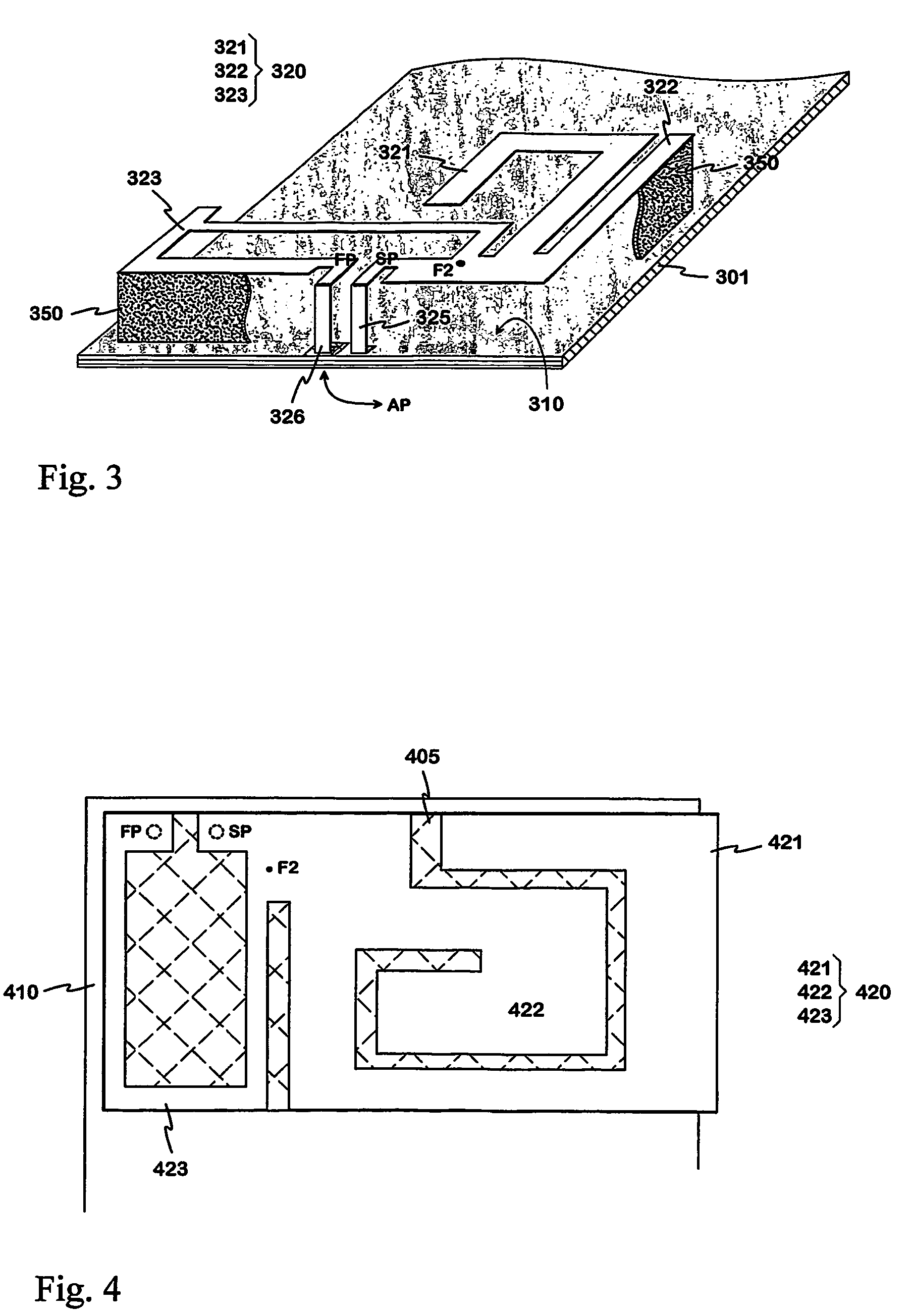
[0024]FIG. 3 shows an example of an internal multiband planar antenna according to the invention. There is a circuit board 301 of a radio device, the conductive upper surface of the circuit board functioning as the ground plane 310 of the antenna. At the one end of the circuit board, above the ground plane, there is the radiating plane 320 of the antenna. The short-circuit conductor 325, which connects the radiating plane to the ground plane, starts from an edge of the radiating plane aside which is called the front side here. The connecting point of this conductor to the radiating plane is called the short-circuit point SP. Close to the short-circuit point on the front side of the radiating plane there is the antenna feed point FP, from which the antenna feed conductor 326 starts. From the feed conductor there is through-hole with ground isolation to the antenna port AP on the lower surfa...


PUM


Abstract

A multiband planar antenna intended for small-sized radio devices and a radio device. The basic structure of the antenna is a two-resonance P1FA, the radiating plane (320) of which has a structural part (321) corresponding to the lowest operating band and a structural part (322) corresponding to the upper operating band. In addition, a loop resonator (323) operating as a radiator is formed in the radiating plane. The ground conductor (325) of the feed line of the loop is at the same time the short-circuit conductor of the PIFA. The second conductor (326) of the feed line is connected to the opposite end of the loop, and it operates as the feed conductor of the PIFA. At the same time the structural part (321) of the radiating plane that corresponds to the lowest operating band is located between the loop and the structural part of the PIFA that corresponds to the upper operating band, in order to reduce interference between them. The resonance frequency of the loop radiator is arranged on the upper operating band of the antenna, for example. Thus the loop improves the matching of the antenna on the upper operating band and the matching and efficiency on the lowest operating band as well. This is based on additional inductance caused by the loop conductor (323) that functions as a part of the feed conductor of the PIFA.

Description

BACKGROUND OF THE INVENTION[0001]The invention relates to a multiband planar antenna intended for small-sized radio devices. The invention also relates to a radio device with an antenna according to the invention.[0002]Models that operate in two or more systems using different frequency ranges, such as different GSM systems (Global System for Mobile telecommunications) have become increasingly common in mobile stations. The basic condition for the operation of a mobile station is that the radiation and receiving properties of its antenna are satisfactory on the frequency bands of all the systems in use. This is a demanding task when the antenna is located inside the covers of the device for comfort of use.[0003]The internal antenna of a small-sized device often has a planar structure, because then the required properties are achieved most easily. The planar antenna includes a radiating plane and a ground plane parallel with it. In order to facilitate the matching, the radiating plan...

Claims


Application Information

Patent Timeline
IPC IPC(8): H01Q1/38H01Q1/24H01Q21/00H01Q1/36H01Q5/00H01Q5/371H01Q7/00H01Q9/04
CPCH01Q1/243H01Q5/371H01Q9/0421
Inventor KORVA, HEIKKIOLLITERVO, PETRA
Owner CANTOR FITZGERALD SECURITIES
Learn More