
Power distribution substation

a substation and power technology, applied in the direction of substations, non-enclosed substations, instruments, etc., can solve the problems of substation floor space occupied by unit substations being burdensome for building space planners or building owners, and errors arising from substation installation “coordination” activities

Inactive Publication Date: 2008-04-01
EATON INTELLIGENT POWER LTD
View PDF4 Cites 22 Cited by
  • Summary
  • Abstract
  • Description
  • Claims
  • Application Information

AI Technical Summary

Benefits of technology

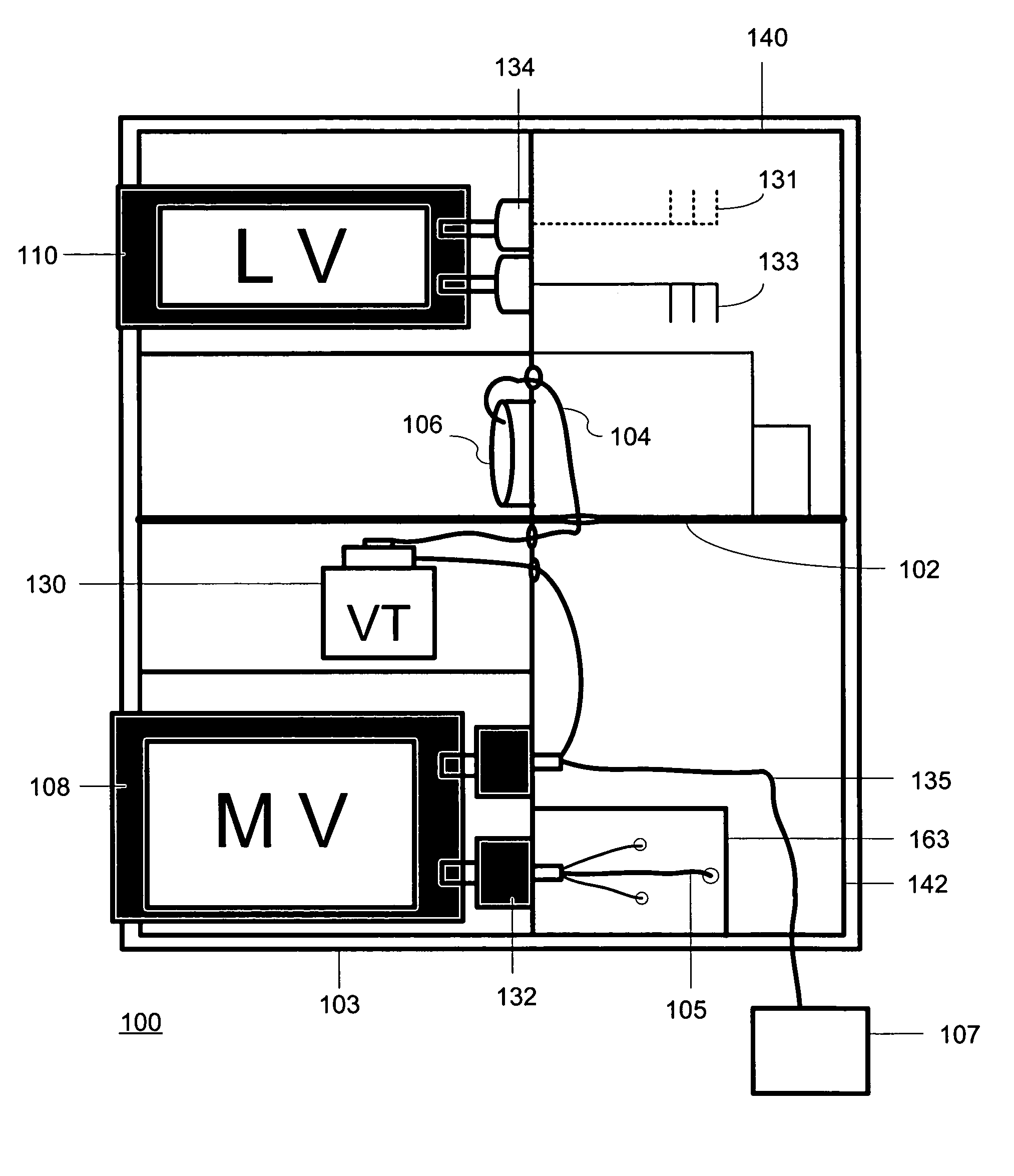
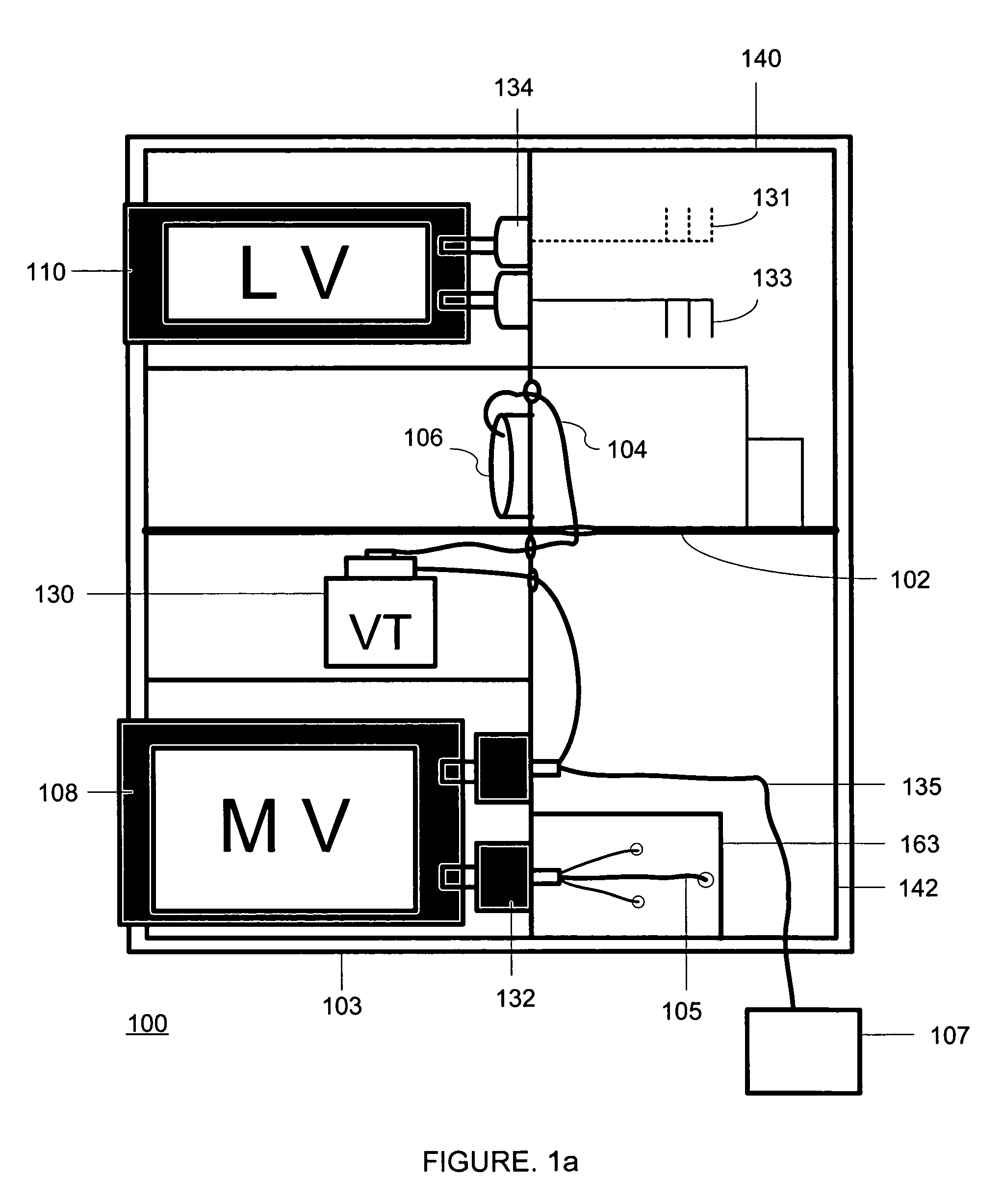
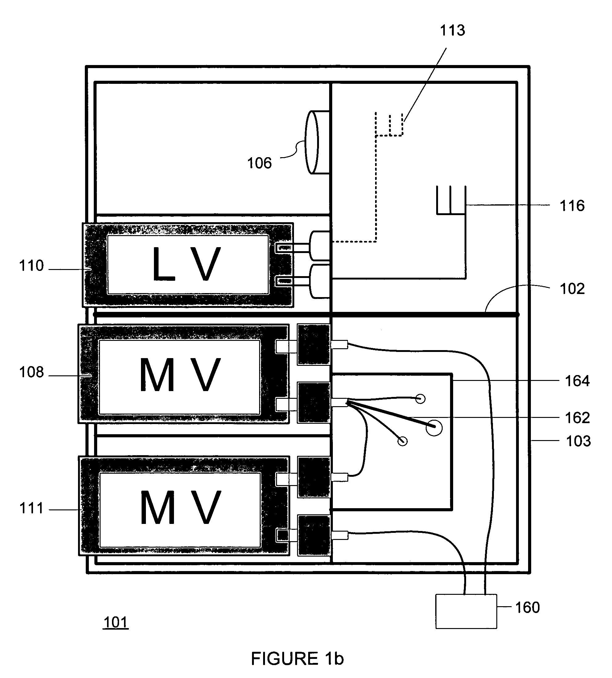
The patent describes an improved power distribution substation that encloses multiple switchgear main breaker cells in a single housing. The low-voltage cells are placed within the same enclosure as the medium-voltage cells, which protect and switch a primary connection to a distribution transformer. The low and medium-voltage cells are vertically arranged within the same enclosure, with an isolation barrier to prevent electrical arcing and heat flow between them. The upper encasement contains a control power transformer powered by the medium-voltage cells. The patent also describes a redundant power distribution system where multiple medium-voltage cells are electrically common on their load sides and coupled to the primary side of a transformer, ensuring continuous power supply even if one of the cells or supply lines fails. The vertical arrangement of the main breaker cells allows for efficient use of space and simplified installation.

Problems solved by technology

One disadvantage of prior art unit substations is associated with the amount of floor space occupied by the substation.
The floor space occupied by unit substations can become burdensome to a building space planner or building owner.
Another disadvantage associated with unit substations is related to errors arising from substation installation “coordination” activities.
Generally, there are at least three distribution substation components that must be carefully coordinated and installed correctly, otherwise errors result.
This imposes severe cost and time constraints on the substation installation.

Method used


Image

  • Power distribution substation
  • Power distribution substation
  • Power distribution substation

Examples


Embodiment Construction

[0028]An improved power distribution substation (also referred to herein as a unit substation) is described. The improved substation encases a plurality of switchgear main breaker cells within a single enclosure. The improved substation provides a floor space savings as compared with prior art substations. Heretofore, medium voltage and low voltage circuit breakers required independent housings. In contrast, the present improved substation allows several different voltage cells (such as low and medium voltage cells) to be housed within the same enclosure. This results in cost and floor space savings as compared to the prior art substations. Because the present improved power distribution substation provides different types of voltage rated main breaker cells in a single structure, the use of multiple structures providing differently voltage rated main breaker cells is eliminated. Hence, overall costs are reduced through use of the improved substation, by providing the equivalent of ...


PUM


Abstract

An improved power distribution unit substation, having a plurality of differing voltage rated main breaker cells, encased within a single housing is disclosed. The improved power distribution substation saves considerable floor space as compared to prior art substations. One embodiment houses a plurality of main breaker cells in a single housing. In this embodiment, a low voltage main breaker cell is vertically positioned above a plurality of medium voltage main breaker cells. Alternatively, a medium voltage main breaker cell is vertically positioned above a plurality of low or medium voltage cells. Improved single-ended and double-ended power distribution substations are disclosed that offer cost and floor space savings as compared to prior art substations.

Description

BACKGROUND[0001]1. Field of the Invention[0002]This invention generally relates to the distribution of electrical power in a network, and more specifically to power distribution substations (commonly referred to as “unit substations”) adapted to receive electrical power at a first voltage and distribute power to a network at a different voltage.[0003]2. Related Art[0004]Electrical power control and distribution systems are commonplace in modern electrical distribution systems. A unit substation is a power distribution substation, which generally receives electrical power at a higher voltage, and distributes power to a network at a lower voltage, such as, for example, in a network used in a hospital or other facility. A unit substation typically consists of three physically and electrically connected components, comprising a primary protective or isolation device, a substation transformer, and secondary distribution equipment.[0005]Several United States-recognized standards address d...

Claims


Application Information

Patent Timeline
Patent Type & Authority Patents(United States)
IPC IPC(8): H02B1/26H02B5/00
CPCH02B7/06
Inventor COURTNEY, THOMAS A.
Owner EATON INTELLIGENT POWER LTD
Learn More