Storage control method for database recovery in logless mode

a storage control and database technology, applied in the field of storage control methods in storage systems having databases, can solve problems such as the inability to guarantee database consistency

Inactive Publication Date: 2008-04-01
HITACHI LTD
View PDF4 Cites 76 Cited by
  • Summary
  • Abstract
  • Description
  • Claims
  • Application Information

AI Technical Summary

Benefits of technology

[0015]Therefore, an object of the present invention is to enable database recovery to be carried out even when a log comprising a DB update history is not prepared.
[0017]The above-mentioned first storage subsystem is constituted such that, when a DB-pair state, which is the pair state of the above-mentioned first DB storage device and the above-mentioned second DB storage device, is a pair-split state, and a difference occurs between the above-mentioned first DB storage device and the above-mentioned second DB storage device, this difference is managed, and when this pair-split state is cancelled, the above-mentioned first storage subsystem, by sending the above-mentioned managed difference to the above-mentioned second storage subsystem, can cause this difference to be updated in the above-mentioned second DB storage device, thereby doing away with the difference between the above-mentioned first DB storage device and the above-mentioned second DB storage device.
[0033]According to the present invention, it is possible for a database to be recovered even when a log comprising a DB update history is not created.

Problems solved by technology

The sequentiality of this data write must be guaranteed in order to avoid a situation in which a transaction-in-progress state remains, making it impossible to guarantee database consistency.

Method used


Image

  • Storage control method for database recovery in logless mode
  • Storage control method for database recovery in logless mode
  • Storage control method for database recovery in logless mode

Examples


Embodiment Construction

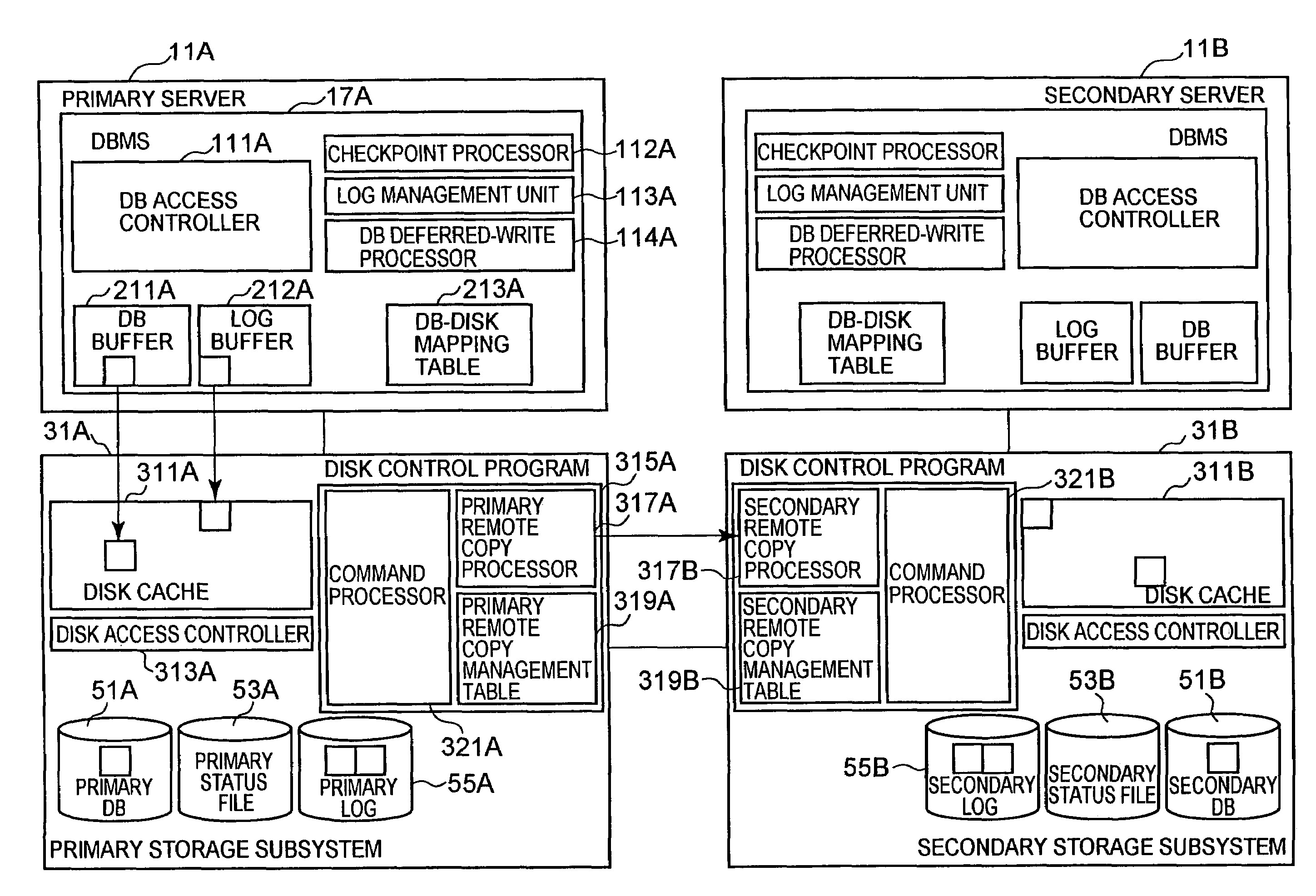
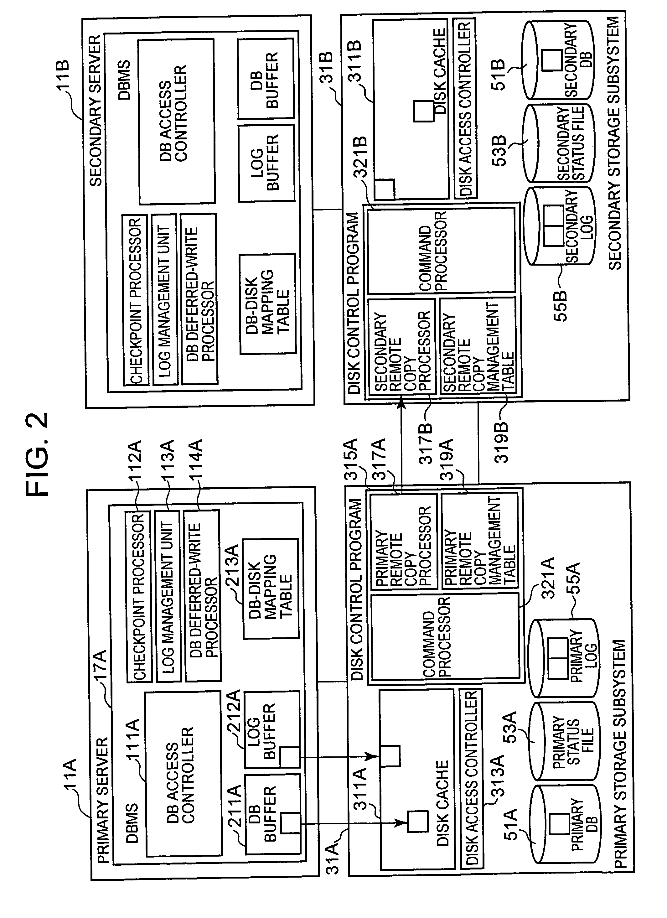
[0046]FIG. 1 shows an example of the overall configuration of a system of a first embodiment of the present invention.

[0047]For example, there is a primary site 30A, and a secondary site 30B, which is geographically separated from the primary site 30A. A client 1 can access, via a first communications network 10, either primary server 11A of the primary site 30A, which will be explained hereinbelow, or a secondary server 11B of the secondary site 30B, which will be explained hereinbelow. The client 1 is a kind of computer, and, for example, can comprise a CPU 3, and a port 9, which is capable of connecting to a storage resource 5 and a first communications network 10. A storage resource 5, for example, is a memory and / or an auxiliary storage device (for example, a hard disk drive, hereinafter HDD). A storage resource 5 is capable of storing data and a plurality of types of computer programs, for example, a computer program 7 for executing a batch operation (hereinafter, a batch oper...


PUM


Abstract

The present invention is constituted so as to enable the recovery of a database even when a log comprising a DB update history is not created. When executing a transaction in the logless mode, a logless-start log is created and written to a primary log VOL 55A at the start of this transaction, and this logless-start log is also written to a secondary log VOL 55B. Thereafter, batch processing is carried out for a DB of a primary DB VOL 51A, and while this transaction is being executed, the pair-split state of the DB VOL is cancelled either prior to the start or after the end of the batch processing, and if the difference between the DB VOLs is eliminated subsequent to the end of batch processing, a logless-end log is created and written to the primary log VOL 55A, and this log is also written to the secondary log VOL 55B.

Description

CROSS-REFERENCE TO PRIOR APPLICATION[0001]This application relates to and claims priority from Japanese Patent Application No. 2006-26676, filed on Feb. 3, 2006 the entire disclosure of which is incorporated herein by reference.BACKGROUND OF THE INVENTION[0002]1. Field of the Invention[0003]The present invention relates to a storage control method in a storage system having a database.[0004]2. Description of the Related Art[0005]For example, in a storage system, which stores a database (hereinafter, DB), there are times when a technique called disaster recovery is employed in preparation for a malfunction. This is a technique in which the data of a certain site is stored in advanced as a replication of another, geographically separate site, and when there is a disaster-caused malfunction at a certain site, work is restored at another site.[0006]Either synchronous remote copying or asynchronous remote copying is carried out between the sites. In synchronous remote copying, data is tr...

Claims


Application Information

Patent Timeline
Patent Type & Authority Patents(United States)
IPC IPC(8): G06F17/30G06F12/00G06F3/06
CPCG06F11/2071G06F17/30312G06F17/30368G06F11/2074G06F11/2076Y10S707/99953G06F16/2358G06F16/22
Inventor KAWAMURA, NOBUO
Owner HITACHI LTD
Why Eureka
Try Eureka