Method of horizontally stacking a stator core within a stator frame

a stator core and horizontal stacking technology, applied in the direction of stator/rotor body manufacturing, magnetic circuit shape/form/construction, magnetic body, etc., can solve the problems of stator core manufacturing complexity, external fixture itself, lamination vibration during generator operation, etc., and achieve the effect of easy sliding into position

Active Publication Date: 2008-04-08
SIEMENS ENERGY INC
View PDF20 Cites 40 Cited by
  • Summary
  • Abstract
  • Description
  • Claims
  • Application Information

AI Technical Summary

Benefits of technology

[0011]In a particular embodiment slide pads are placed between laminations and the extended keybars. This allows for the laminations to be more easily slid into position. The slide pads will initially be placed between the laminations and the extended keybars, however, slide pads may also be used on the non-extended keybars, to which the laminations will engage when they are being slid into the stator frame. In certain embodiments the slide pads are removed after the laminations are slid into position.

Problems solved by technology

Improper clamping can result in lamination vibration during generator operation, due to magnetic impulses and / or core elliptical dilation.
However, the large size of the stator core results in stator core manufacturing complexities, including the need for generous floor space, high crane requirements, manufacturing lead time and other associated manufacturing difficulties.
If, on the other hand, the stator core is manufactured in an external fixture, the external fixture itself adds to the manufacturing costs and requires additional floor space on site and still requires the use of heavy cranes.
This can lead to large scale rearrangement and imposition of the stator core and surrounding area for substantial periods of time.
Using the prior art, stacking a core horizontally is extremely difficult with lamination aggregates, and large aggregates, such as donuts, is essentially precluded.
This is particularly needed in pre-existing stator frames, not initially designed for such assemblies, where vertical stacking is not practicable and where room is otherwise limited.

Method used


Image

  • Method of horizontally stacking a stator core within a stator frame
  • Method of horizontally stacking a stator core within a stator frame
  • Method of horizontally stacking a stator core within a stator frame

Examples


Embodiment Construction

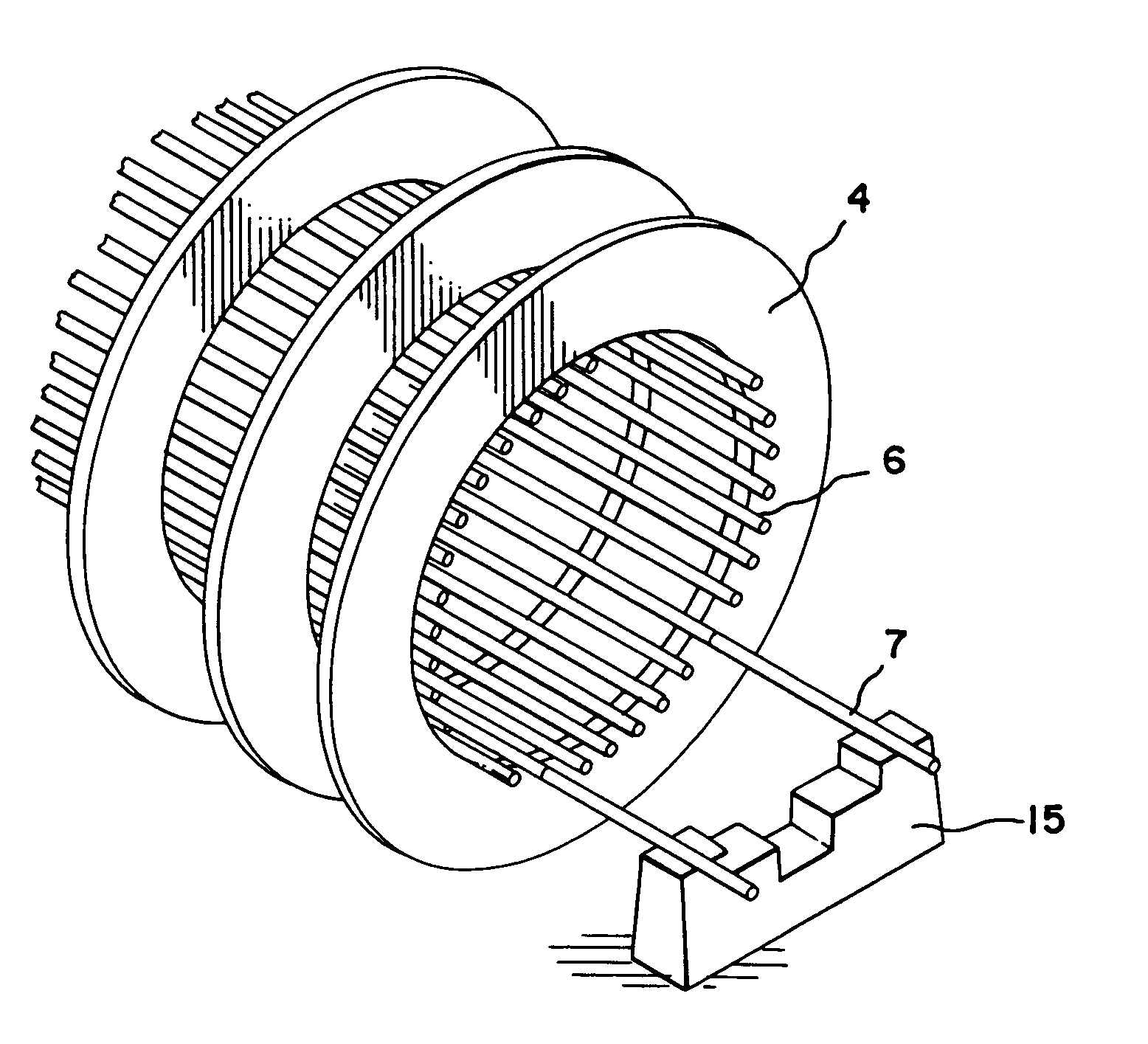
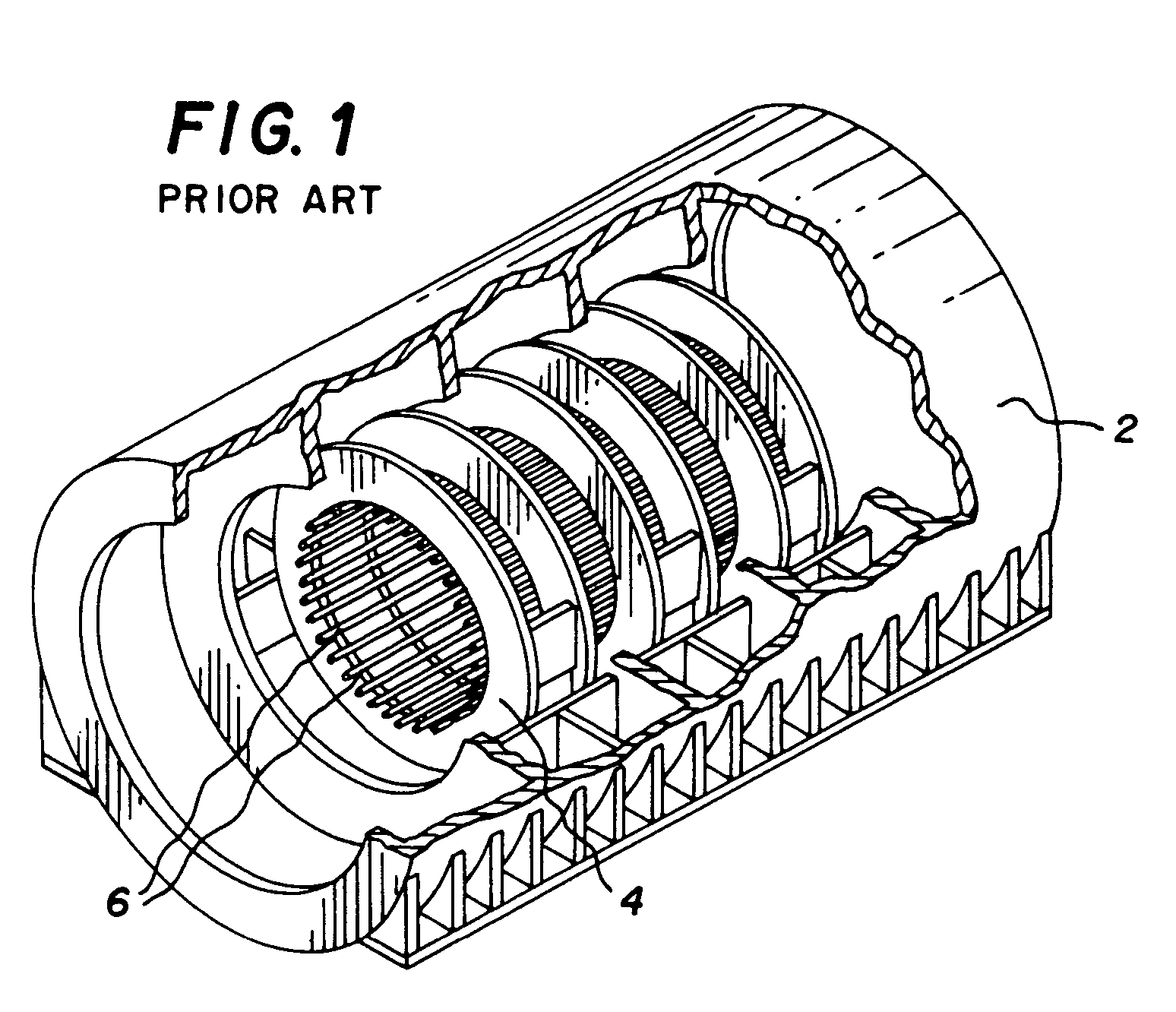
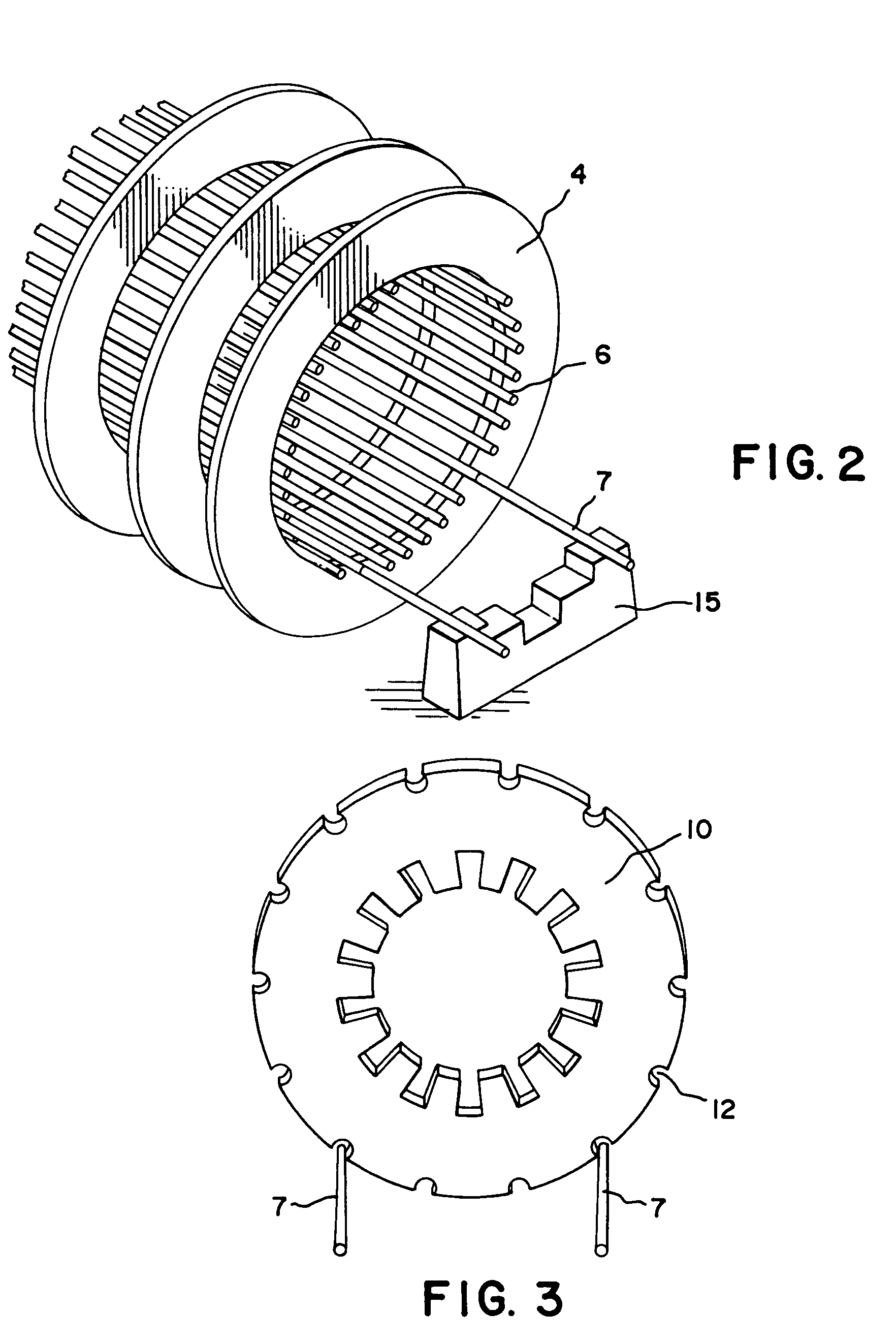
[0021]The present invention comprises a method and apparatus for stacking laminations and donuts horizontally by extending two or more keybars and using the extended keybars as rails to guide the laminations and donuts into position. Stator core donuts have hitherto been stacked vertically, using gravity to guide the donuts into place. There often arises, however, a need to stack the stator core horizontally. This creates problems, since stacking individual laminations is time consuming, while stacking donuts horizontally is next to impossible due to their size and manufacturing variations.

[0022]The present invention helps resolve this dilemma by providing keybar extensions that act as rails to slide the laminations and / or donuts into place. Since the keybars are ultimately going to hold the laminations in place in the stator frame, the keybar extensions provide a perfect method of guiding the laminations into position.

[0023]The keybar extensions can support the laminations and donu...


PUM

PropertyMeasurementUnit
Radial Forcesaaaaaaaaaa
forcesaaaaaaaaaa
sizeaaaaaaaaaa

Abstract

The present invention provides a method for the horizontal stacking of laminations 10 and donuts to form a stator core. A stator generator frame 2 has multiple keybars 6 that run the axial length of the frame. The laminations 10 have grooves 12 there-in that engage the keybars to provide a secure fit of the laminations to the generator frame. By extending two or more of the keybars 6, these extensions 7 may be used as rails on which the laminations may be horizontally inserted into the stator frame.

Description

CROSS-REFERENCE TO RELATED APPLICATIONS[0001]This invention claims priority to U.S. Provisional application 60 / 565,307 filed Apr. 26, 2004 entitled Methods and Apparatuses for Assembling Generator Stator Cores, which is incorporated herein by reference. This invention is further related to U.S. applications: Apparatus and Method for the Installation of a Pre-Assembled Stator Core, by Allen, et al.; Method and Apparatus of the Mounting of and Circumferential Displacement of Radial Forces in a Stator Core Assembly, by Sargeant et al.; Horizontal Assembly of Stator Core using a Central Rail Structure by Majernik et al.; all filed herewith and all incorporated herein by reference.FIELD OF THE INVENTION[0002]The present invention relates to the assembly of generator stator cores. More particularly, the invention relates to the horizontal assembly of a stator core using keybar extensions as rails for the placement of laminations and donuts.BACKGROUND[0003]The generator stator core is the ...

Claims


Application Information

Patent Timeline
Patent Type & Authority Patents(United States)
IPC IPC(8): H02K15/00H02K1/12H02K1/18H02K15/02
CPCH02K1/185H02K15/028Y10T29/49009Y10T29/49012Y10T29/5168Y10T29/49078Y10T29/53143Y10T29/49913
Inventor MAJERNIK, TOMBAUER, JAMESSARGEANT, BARRYDAILEY, GEORGE
Owner SIEMENS ENERGY INC
Why Eureka
Try Eureka